Reverse engineering a Fujitsu Air Conditioner Unit – A test unit arrives
So my test unit arrived!
I get it on my bench, and test out my theory – if I’m right, it should boot up and start sending commands when the buttons are pressed.
I was wrong.
The unit just sits there flashing “9C” for a couple of minutes, then failing over to a “C0 12” error. The Oscilloscope was no use either – I just saw a constant 12V on the signal wire.
Hmmm.
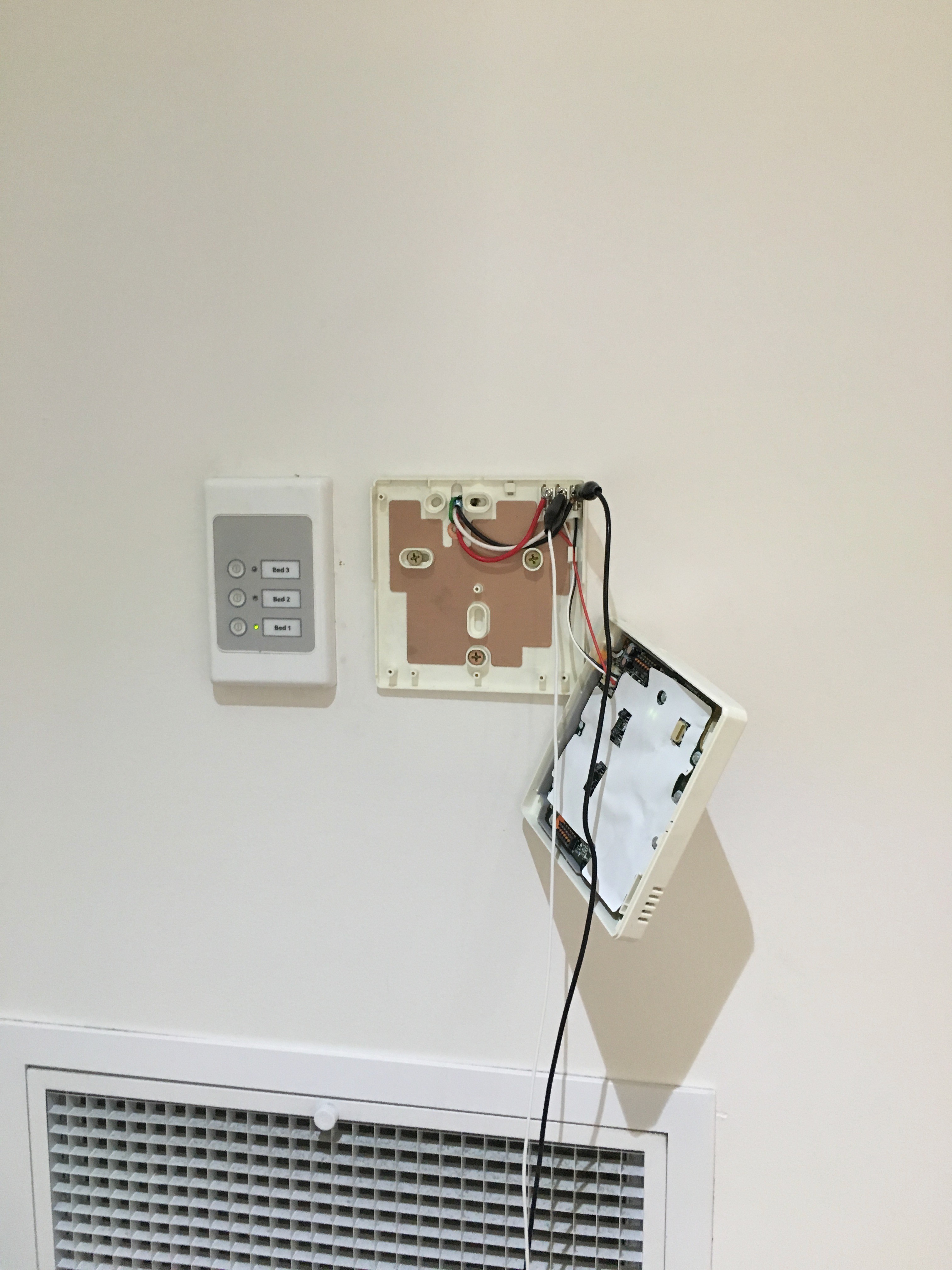
Looks like I’ll have to pull off the real wall unit.
Using some wire and alligator clips, I extended the wires so I could reach them with the scope.
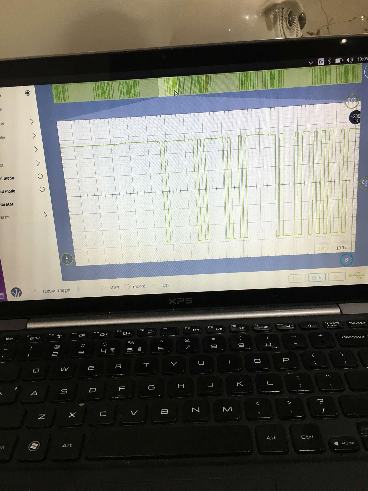
This time I got somewhere – I could see a signal!
The pulse width is around 1.04ms, going from 12V to 0V. Weird.
I go distracted for a while trying to decode the protocol – is there start bits and stop bits? What about a parity bit?
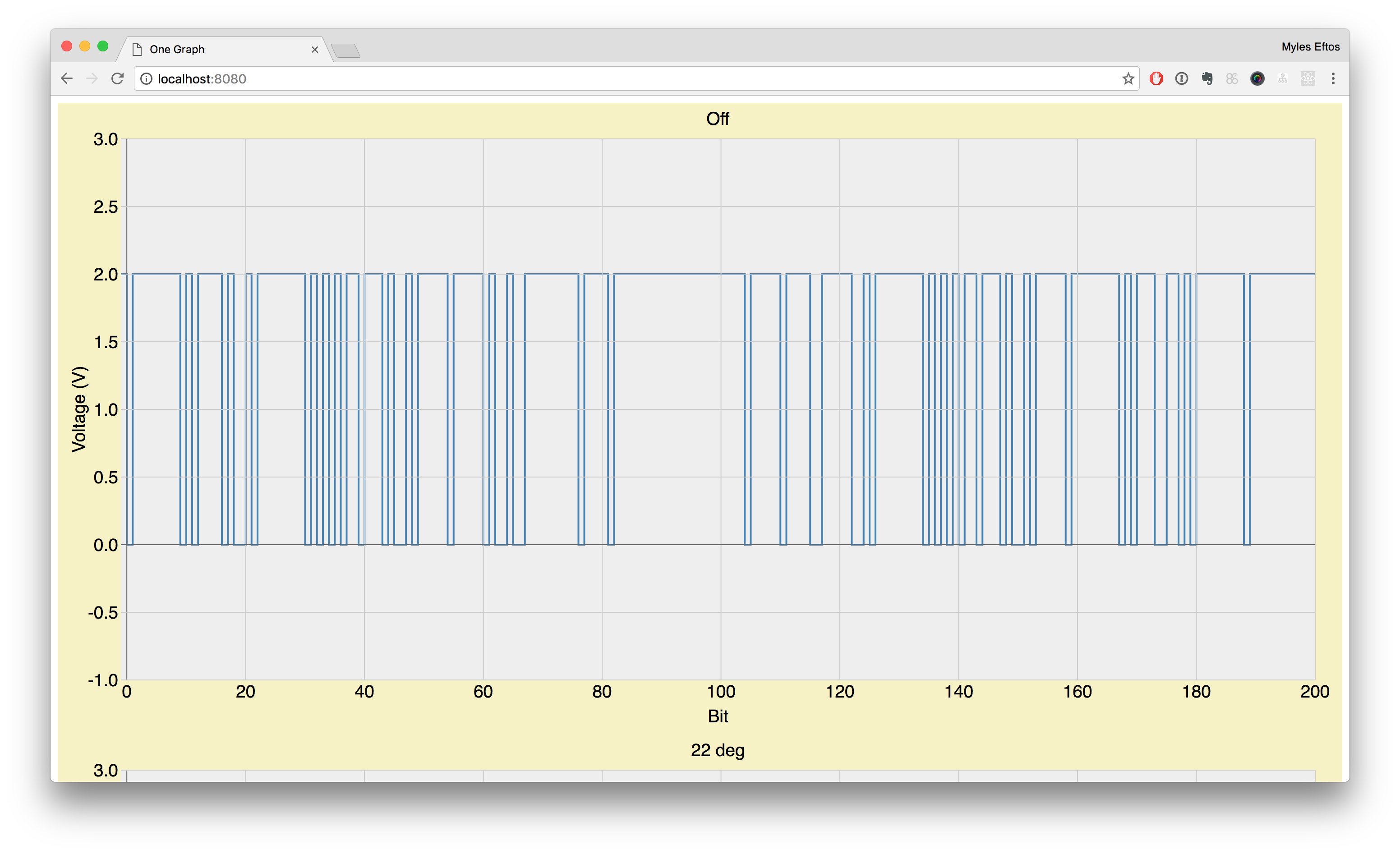
I knocked together a quick D3 script (I’m a web developer, remember – I use web technology for a lot of this stuff because that is what I’m used to) to display the wave form. First, I wrote a ruby script that created a CSV file of just the transitions. There are two entries for each transition – a 0V and 12V value – so the graph ends up looking like a binary stream.
I then wrote another script that aligned the stream so each pulse was exactly 1.04, and each pulse hight was 12V or 0v. Finally, I scaled everything so the pulse width was 1, as this made reading the graphs easier.
I ended up with some pretty graphs like this:
There was still a problem though – I didn’t have a baseline for the communications.
I knew that the control unit didn’t send any data unless it was connected to the outside unit. I also knew that changing the temperature changed some of the bits in the data stream, so clearly there was some half-duplex serial communication going on. I needed to find out what the outdoor unit sent to initialise the control unit…


