Upgrading a Kegerator
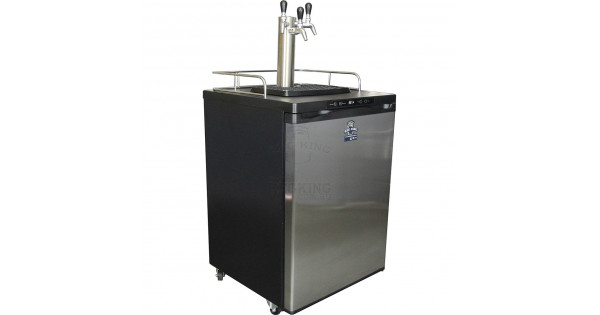
A mate of mine gave me a Keg Master Series 3 Kegerator that he was no longer using, which was a stroke of luck. Just before we moved house in 2023, I turned off my old kegerator.
A kegerator is just a fridge with beer taps attached, in which you can store beer kegs.
That kegerator was a home-build - a bar fridge that I drilled some holes in. One of the holes was quite large and exposed the inner foam of the fridge. The inner foam, it turns out, is a great place for mould to grow, particularly when wet and warm which coincidently happens when you turn off a fridge.
Anyway, I was now no longer kegerator-less.
However, there were a couple of issues:
- The seven-segment display was missing a couple of segments. I pulled it apart and fixed a couple of dry joints.
- If it lost power it would revert to a very low Fahrenheit temperature; which would have just been annoying, except:
- It would freeze everything kept in it. Even setting the temperature controller to 3 or 4 degrees. After losing a 19L batch of beer, I decided to replace the faulty temperature controller.
Does your kegerator need to be on the Internet?
No. And it’s technically not - it’s on my Intranet (or local cloud as marketing people would call it).
I decided that this project needed to tick the following boxes:
- Minimise the number of modifications to the existing hardware. I wanted to include a display and I wanted the buttons to function.
- I wanted to be able to monitor the temperature in Home Assistant, so I could add alarms if something weird happened
- It should remember the last temperature settings and default back to the last state.
- I’d like it to keep the temperature within 1 degree of the set-point
I was clearly going to replace the control board, but I wanted to reuse the existing connectors. The seven segment display can go - LCDs are dirt cheap, and can convey more information.
First step: design a new circuit. There are three unknowns to solve: the temperature sensor, the relay that drives the compressor and the buttons.
The buttons
The buttons turned out to be pretty easy, there are five pins: one is common and three of the other ones are wired to the buttons. A few minutes with a multimeter mapped them out.
Driving the relay
The relay was only marginally tricker. The kegerator has a schematic stuck on the back, which suggested there was a daughter board with a relay on it. I pulled the back off and found the board and pulled it out to inspect it.
This board must be used in other products as it has provisions for a second relay - perhaps for a heater in a fermentation chamber?
The relay is driven by a transistor, which presented a small problem.
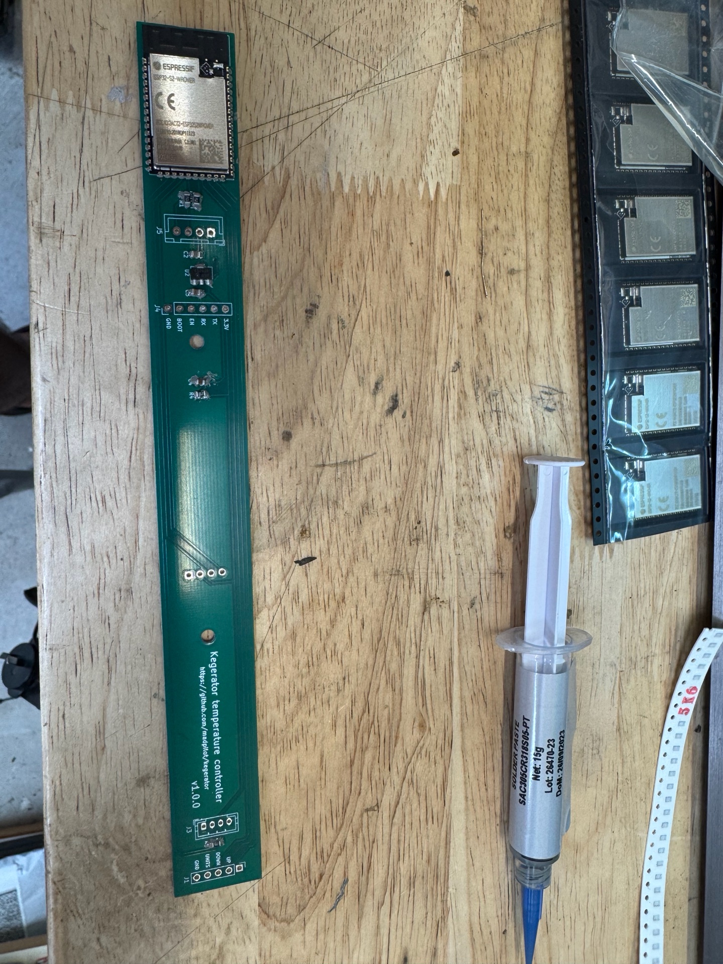
I had a bunch of ESP32-S2-WROOMs in stock, so I decided to use that as the brains. However, they can only source 3.3V. The existing controller is all 5V logic.
Given the transistor is a current-driven device I just needed to find a resistor that matched the current flowing through a 2.2k resistor that was driving the base of the transistor.
Measuring the voltage drop across the resistor:
$$V_{drop} = 4.3V$$$$4.3V/2200\Omega = 0.00195A$$
$$3.3V-(5V-4.3V) = 2.6V$$
$$2.6V/0.00195A = 1,333.333\Omega$$
So, something close to a 1.3k resistor. I tried it out on a breadboard, and it all worked perfectly.
Reading the temperature
Finally, I need to work out what to do about the thermistor. The current one was unmarked, but was probably a k-type? Given I wanted to make this fridge more accurate, trying to calibrate an unknown thermistor didn’t seem like a great idea. Not to mention there was a bunch of other circuitry that would need to be designed and sourced. Also: a had a bunch of Dallas DS18B20 lying about.
The next problem: the wiring to the thermistor has just two wires and the DS18B20 is a three-wire device. The existing wire is lodged in the case of the fridge and seemingly glued in, so replacing it wasn’t really an option.
Luckily, it is possible to run the DS18B20 using just two wires. By grounding the VCC pin, the chip will go into parasitic power mode, where a capacitor charges while the data line is high, which gives it enough power to read its internal ADC, convert the number to a temperature, and spit it back over the i2c bus.
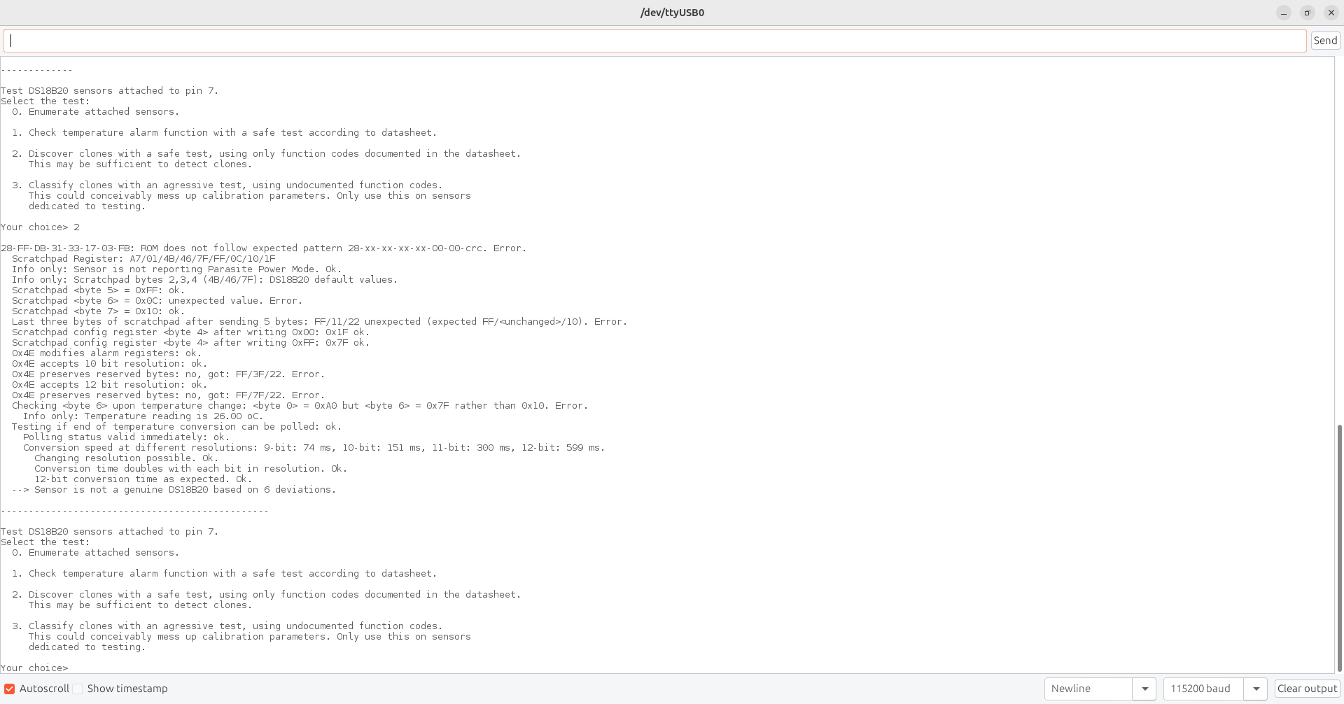
Hilariously, I burnt an hour or two trying to get this to work. It turns out the cheap DS18B20s I bought off Aliexpress were knock-offs. After switching them out for some other ones (which were also fakes, but ones that seem to support parasitic power), we were good to go.
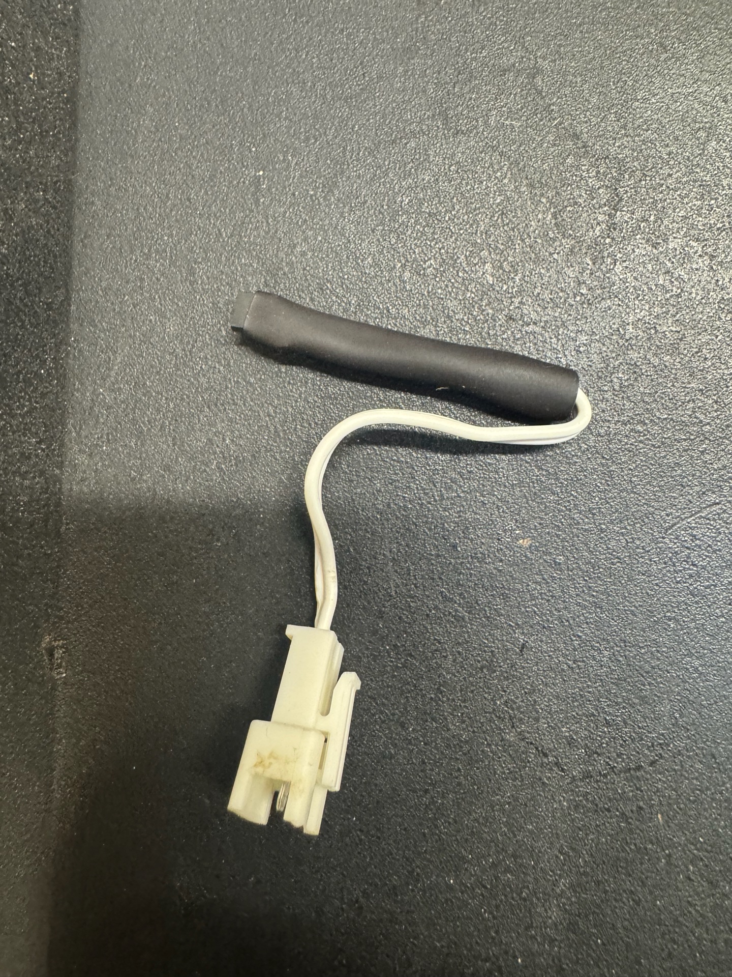
The old sensor was terminated with a connector, so I just cut the end and wired in the new temperature sensor with some heat-shrink to cover my sins.
You can download the KiCad files on my GitHub.
Let’s get cooking
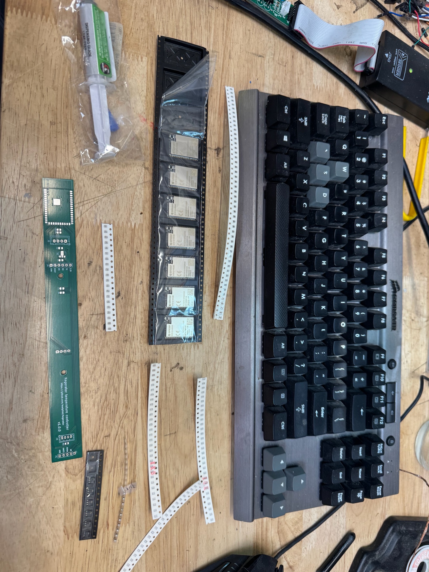
It’s been a while since I’ve done SMDs and I stupidly didn’t order a stencil. Free handing solder paste is not fun.
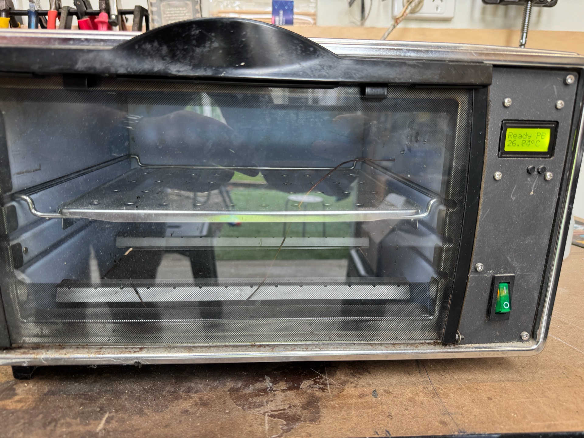
But, I eventually got the board up. After a few minutes in the toaster oven (and a couple of fixes with the hot air gun) we were ready to roll.
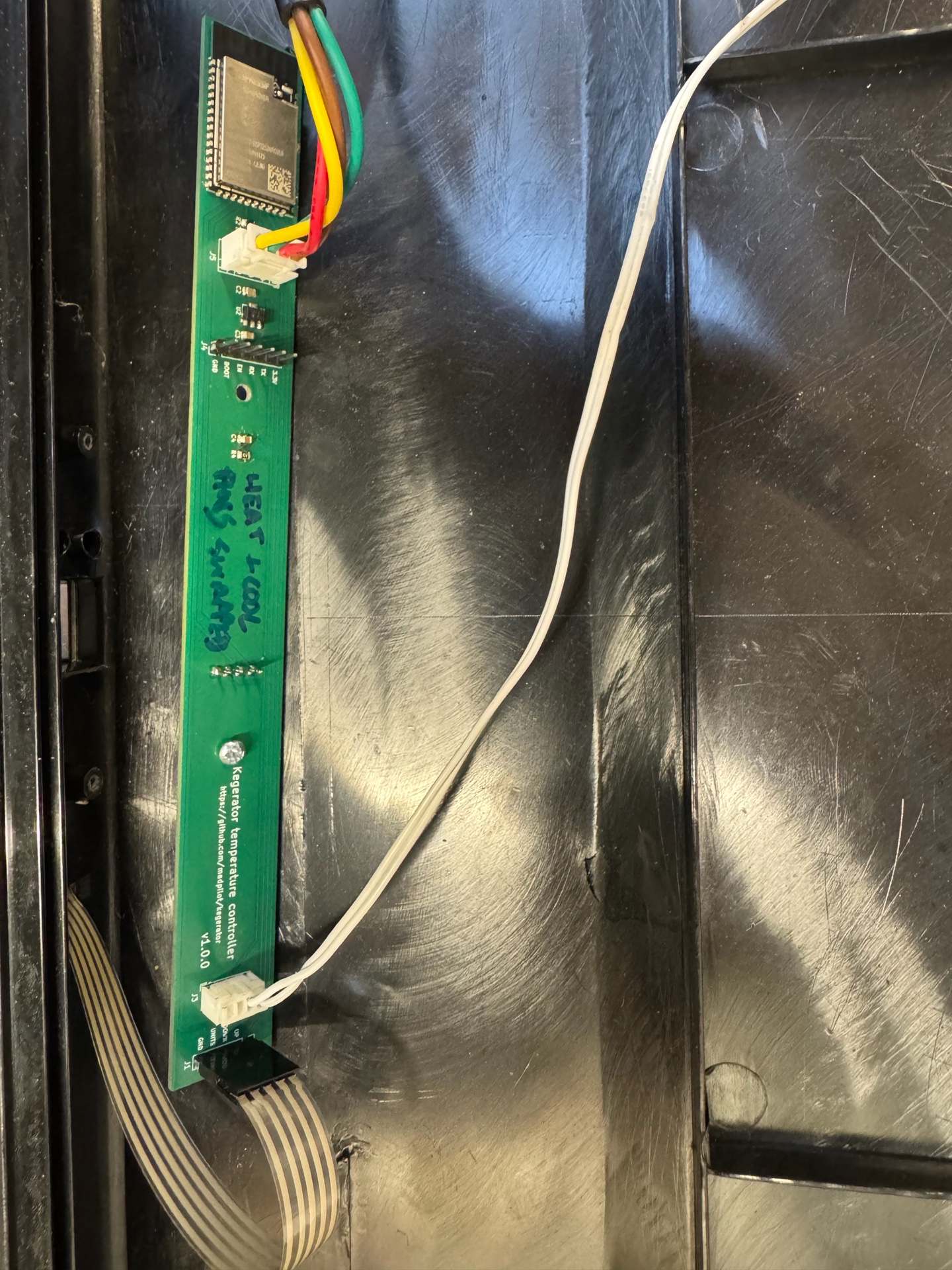
Bodge wires
Everything worked perfectly first time.
Kidding. Of course, it didn’t.
The biggest issue was some idiot (me) didn’t read the data sheet correctly and failed to realise that pin 26 is internally reserved for use by SRAM. My original schematic has this as the GPIO that turned on the cooling. Kinda important.
Thankfully I had designed the board to break out the unused heater wire in the wiring harness. The heater was routed to a usable pin, so swapping the wires in the connector and a quick firmware reconfiguration got me out of trouble.
The second issue was the pin I originally selected for the temperature up button was also internally connected to something. Whatever it was had just enough resistance to stop the button from triggering.
I added a couple of bodge wires to move the button to a different GPIO. Since the original cooling pin was no longer in use I could use it as a solder point and I could flip sides to make the wiring a bit neater.
Firmware
I’m just using esphome for this stuff now - it has all the sensors, a PID implementation, can render stuff to displays and has over-the-air updates.
At the time of writing this is the YAML:
esphome:
  name: kegerator

esp32:
  board: esp32-s2-saola-1

i2c:
  sda: GPIO17
  scl: GPIO16

font:
  - file: "gfonts://Roboto"
    id: font_large
    size: 18
  - file: "gfonts://Roboto"
    id: font_small
    size: 8

display:
  - platform: ssd1306_i2c
    model: "SSD1306 128x32"
    lambda: |-
      float current_temperature = id(kegerator_pid).current_temperature;
      float target_temperature = id(kegerator_pid).target_temperature;

      if(id(kegerator_pid).mode == CLIMATE_MODE_COOL) {
        if(!std::isnan(current_temperature)) {
          it.printf(64, 0, id(font_large), TextAlign::TOP_CENTER, "%.1f°C", current_temperature);
        } else {
          it.printf(64, 0, id(font_large), TextAlign::TOP_CENTER, "--°C");
        }
      } else {
          it.printf(64, 0, id(font_large), TextAlign::TOP_CENTER, "Off");
      }

      if(!std::isnan(target_temperature)) {
        it.printf(64, 32, id(font_small), TextAlign::BOTTOM_CENTER, "%.1f°C", target_temperature);
      } else {
        it.printf(64, 32, id(font_small), TextAlign::BOTTOM_CENTER, "--°C");
      }

one_wire:
  - platform: gpio
    pin: GPIO15

sensor:
  - platform: dallas_temp
    id: temperature
    name: "Temperature"
    update_interval: 1s
    unit_of_measurement: "°C"
    device_class: "temperature"
    state_class: "measurement"
    accuracy_decimals: 1
    filters:
      - exponential_moving_average:
          alpha: 0.8
          send_every: 30

binary_sensor:
  - platform: gpio
    id: btn_temp_up
    pin:
      number: GPIO14
      inverted: true
      mode:
        input: true
        pullup: true
    filters:
      autorepeat:
        - delay: 1s
          time_off: 100ms
          time_on: 100ms

    on_click:
      lambda: |-
        float target_temperature = id(kegerator_pid).target_temperature;
        auto call = id(kegerator_pid).make_call();
        call.set_target_temperature(target_temperature + 0.1);
        call.perform();

  - platform: gpio
    id: btn_temp_down
    pin:
      number: GPIO21
      inverted: true
      mode:
        input: true
        pullup: true
    filters:
      autorepeat:
        - delay: 1s
          time_off: 100ms
          time_on: 100ms
    on_click:
      lambda: |-
        float target_temperature = id(kegerator_pid).target_temperature;
        auto call = id(kegerator_pid).make_call();
        call.set_target_temperature(target_temperature - 0.1);
        call.perform();

  - platform: gpio
    id: btn_units
    pin:
      number: GPIO20
      inverted: true
      mode:
        input: true
        pullup: true
    on_click:
      then:
        lambda: |-
          auto call = id(kegerator_pid).make_call();
          if(id(kegerator_pid).mode == CLIMATE_MODE_COOL) {
            call.set_mode("OFF");
          } else {
            call.set_mode("COOL");
          }
          call.perform();

button:
  - platform: template
    name: "Kegerator PID Climate Autotune"
    on_press:
      - climate.pid.autotune: kegerator_pid

output:
  id: compressor
  platform: slow_pwm
  pin: GPIO18
  period: 1200s

climate:
  - platform: pid
    id: kegerator_pid
    name: "Kegerator"
    sensor: temperature
    default_target_temperature: 7°C
    cool_output: compressor
    visual:
      min_temperature: -7
      max_temperature: 32
      temperature_step: 0.1
    control_parameters:
      kp: 0.19714
      ki: 0.00028
      kd: 34.89431

logger:

api:
  password: ""

ota:
  - platform: esphome
    password: ""

wifi:
  ssid: !secret iot_wifi_ssid
  password: !secret iot_wifi_password

  ap:
    ssid: "Kegerator"
    password: ""
The latest version can be found on my GitHub.
Breaking is down, temperature reading is done by the one_wire and sensor sections. I’m using an exponential moving average filter to clean up the readings. Exponential moving average filters are memory efficient, as you only need to store the last value. The new value is found by the following formula:
$$T_{t} = \alpha x_{t} + (1 - \alpha)T_{t-1}, t > 0$$
This is just a fancy way of saying “The new temperature is the new reading times a weighting, plus the last temperature times the inverse weighting”. I picked a weight of 0.8, so the temperature is biased towards the new reading.
The climate section is the PID controller. You will note the default_target_temperature setting. From the esphome documentation:
The default target temperature (setpoint) for the control algorithm. This can be dynamically set in the frontend later.
If it’s never been set, it’ll use the value 7, but the frontend will automatically set it to the previous value. I have verified this recently, as a contractor killed the power (including from the battery), and the kegerator reverted to the last set-point. Goal #3 achieved!
The output section defines the pin that the drives the compressor. I’m using the slow_pwm setting, which the esphome docs do a better job of explaining it than I can:
Similar to PWM, the Slow PWM Output platform allows you to control GPIO pins by pulsing them on/off over a longer time period. It could be used to control a heating element through a relay where a fast PWM update cycle would not be appropriate.
The buttons are defined in the binary_sensor section. I’m using the internal pull-ups saving me 4 resistors. I also added an auto-repeat filter, which will increase or decrease the set-point faster if you hold the buttons down for 1s. Using the existing buttons: Goal #1 achieved!
The i2c, display and font section drive the display. Esphome is pretty clever - it can automatically download, and convert fonts to embed and display. The heavy lifting is done in the lambda block. The code is straight up C++. If the kegerator is in cooling mode, it displays the current temperature. Otherwise, it just displays the word “Off” on the first line. It also displays the target set-point on the second line.
Finally, the api, ota and wifi sections allows the kegerator to be controlled by home assistant (Goal #2 achieved!), and allows the firmware to be updated over-the-air.
Tuning the PID
The control parameters are pretty specific, and—shockingly—I didn’t come up with the numbers.
The Esphome PID plugin has an auto-tune function, that is triggered by a button in Home Assistant. It runs an “adaption of the Ziegler-Nichols method with relay autotuning (Åström and Hägglund)”. To autotune the kegerator, I filled a 19L keg with water, and ran the autotune. It took awhile, but it came up with the numbers in the YAML.
[13:21:03][I][pid.autotune:163]:   Calculated PID parameters ("Ziegler-Nichols PID" rule):
[13:21:03][I][pid.autotune:164]:
[13:21:03][I][pid.autotune:165]:   control_parameters:
[13:21:03][I][pid.autotune:166]:     kp: 0.19714
[13:21:03][I][pid.autotune:167]:     ki: 0.00028
[13:21:03][I][pid.autotune:168]:     kd: 34.89431


[13:21:03][D][pid.autotune:176]:   Alternative Rules:
[13:21:03][D][pid.autotune:208]:     Rule 'Ziegler-Nichols PI':
[13:21:03][D][pid.autotune:209]:       kp: 0.14786, ki: 0.00013, kd: 0.00000
[13:21:03][D][pid.autotune:208]:     Rule 'Pessen Integral PID':
[13:21:03][D][pid.autotune:209]:       kp: 0.23000, ki: 0.00041, kd: 48.85204
[13:21:03][D][pid.autotune:208]:     Rule 'Some Overshoot PID':
[13:21:03][D][pid.autotune:209]:       kp: 0.10941, ki: 0.00015, kd: 51.64358
[13:21:03][D][pid.autotune:208]:     Rule 'No Overshoot PID':
[13:21:03][D][pid.autotune:209]:       kp: 0.06571, ki: 0.00009, kd: 29.07859
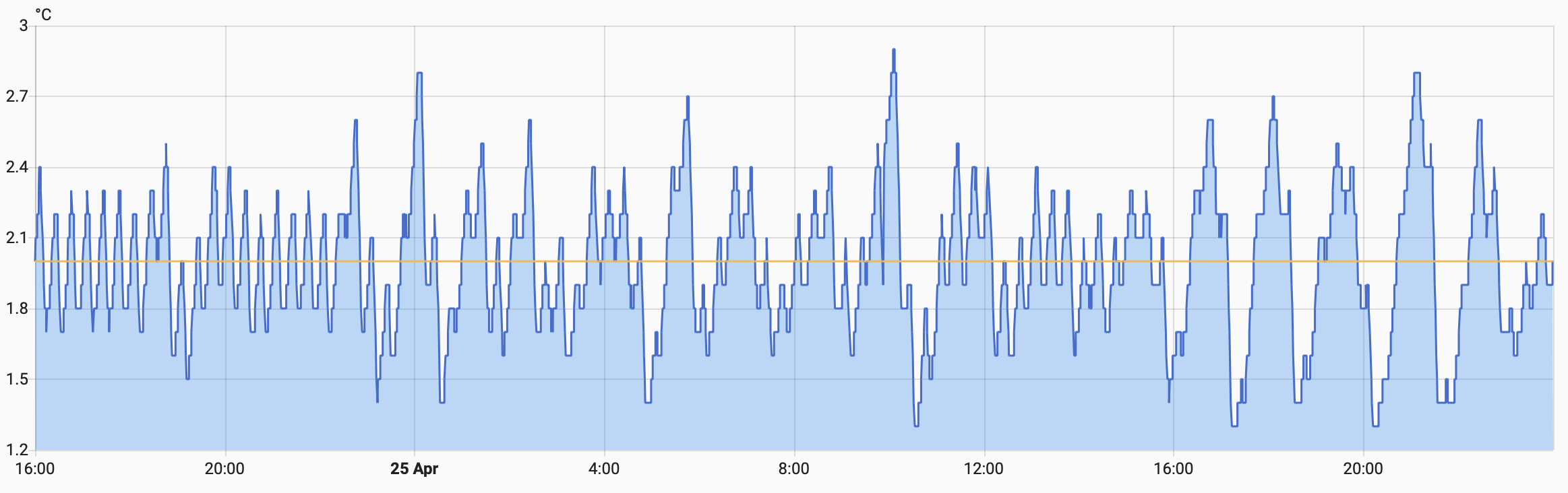
So how does it perform? Pretty well. The temperature stays with-in ±1°C of the set point (Goal #4 achieved!), and the duty-cycle seems to hover around 50%, which means the compressor is on for 10-minutes, then off for 10-minutes. Most importantly, none of my drinks have frozen!