Converting a Makibox – Building the Y-axis
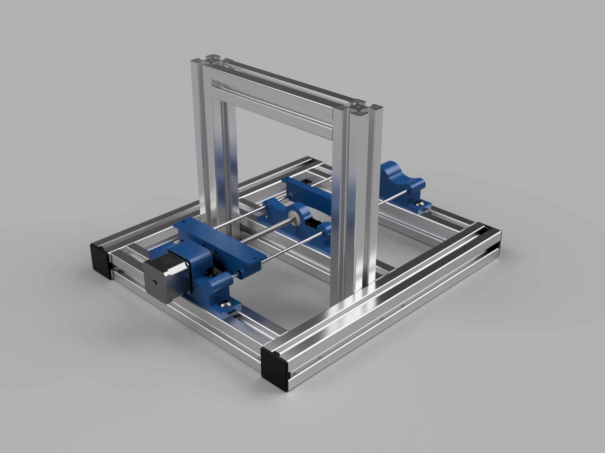
I’ve now built the aluminium frame and completed the Y-axis. Of course, this was not without it’s problems.
Firstly, I misordered – I was one set of uprights short. This may not be a massive problem though, as I hadn’t taken into account the size of the spindle when designing the X-axis, and it wouldn’t have fitted in the configuration I had designed for – That’s what you get for forging ahead with out good engineering drawings.
Other minor issues were easily fixed by reprinting some parts – I added limit switches into the motor and bearing holders (though I haven’t worked out how to make the switch on the bearing holder work yet), I made the driver carriage wider so the whole anti-backlash nut fitted completely and I changed the shape of the passenger carriage so it could slide over the entire stroke.
Everything went together quite well – I did my best to square everything up, using a shim I printed – the holders may not be exactly in the middle, but they are all consistently out, which is the main thing.
I was a little concerned that both carriages were rotating around the z-axis, but realised that was because they weren’t joined yet, so there was only two points of contact, rather than four.
To fix that, I cut out a 205mm x 205mm MDF spoil board, and attached it using a 0.33mm feeler gauge squared it against one of the uprights.
I’m not sure I can do more alignment without having a X-axis, which requires a redesign.
See the video below for the test! (Excuse the upright video – I need to get an iPhone holder)