@madpilot makes

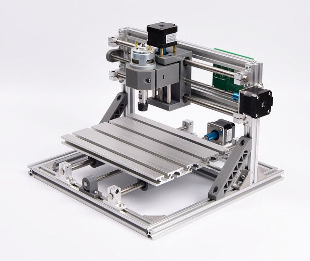
Converting a Makibox into a PCB Mill – The Y-axis has arrived!

After cancelling the order that was clearly never going to arrive, an order from a new supplier has completed the y-axis for my homebuilt CNC mill.

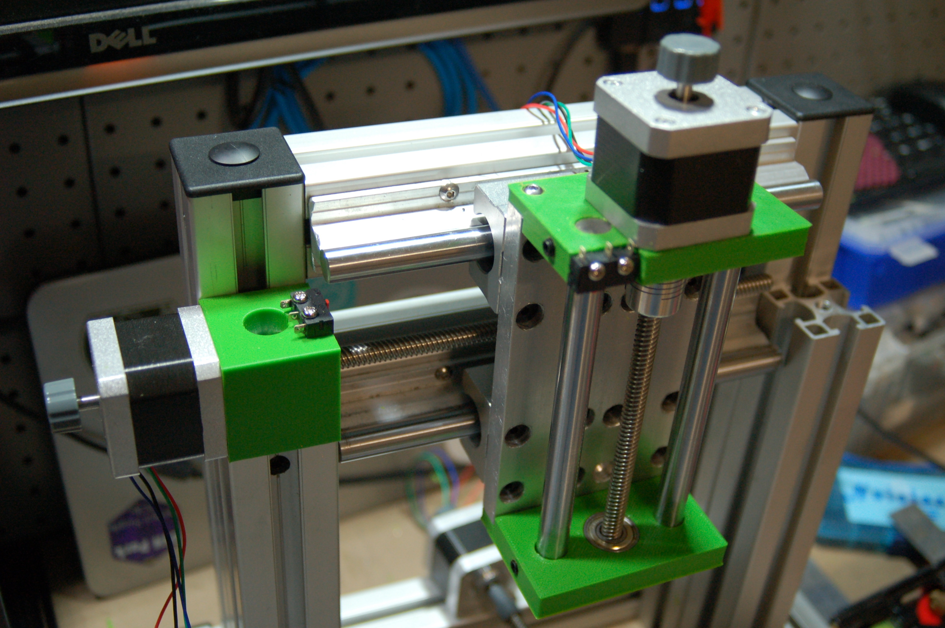
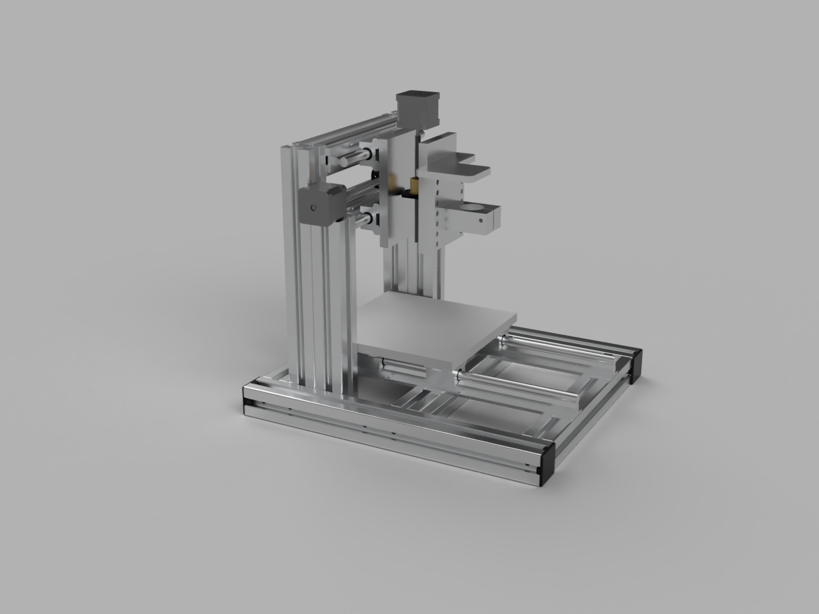
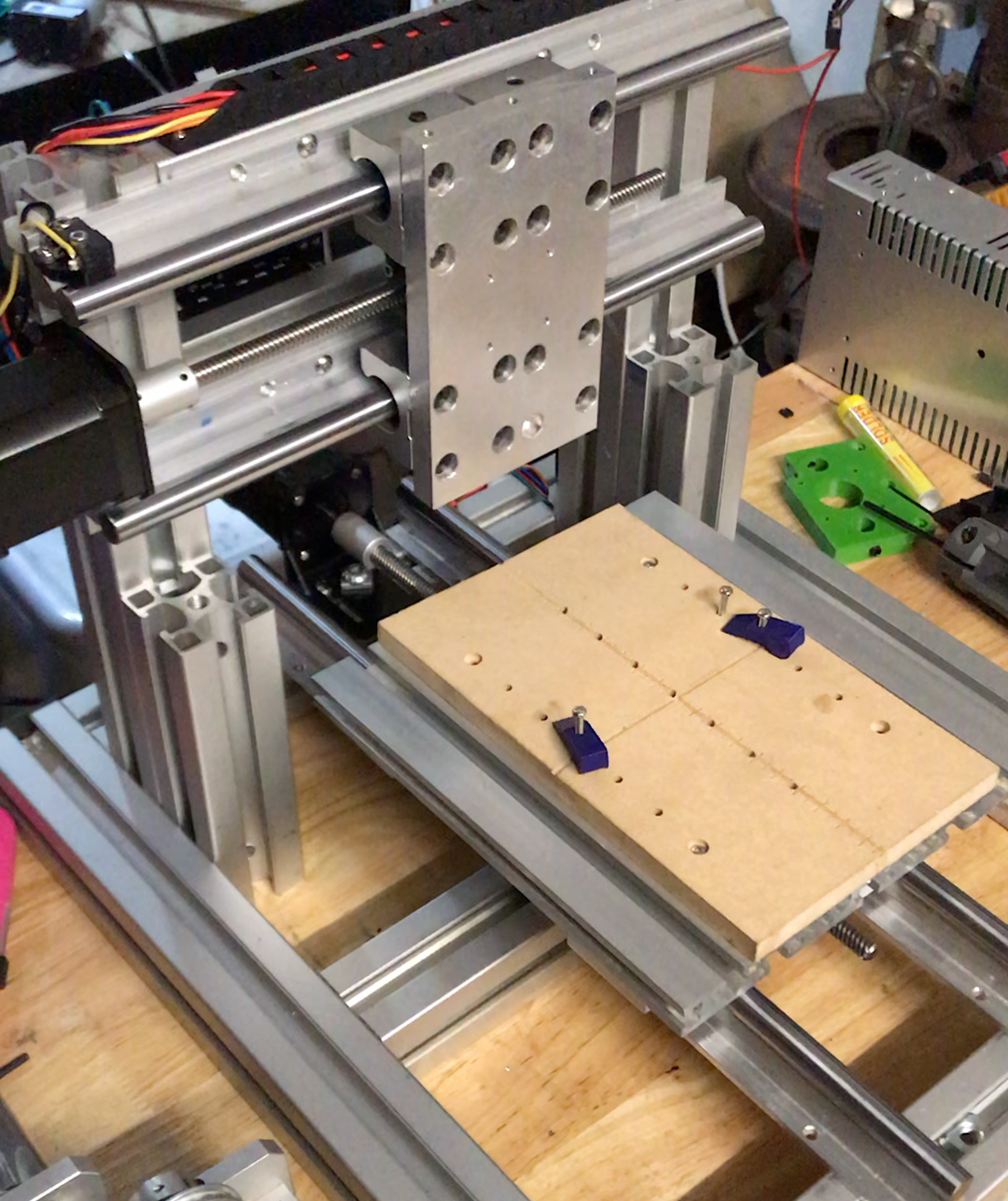
I used left over aluminium to create four adapters to hold the base board to the slides. I’m using a 200x180mm extrusion as it gives me a bunch of work piece holding options.

Once I assembled everything, I did notice a couple of issues.

The spindle isn’t centered

The spindle is about 20mm off centre in the Y direction, so I needed to adjust the position of the front brackets to stop them falling off when the y-axis was at full stroke.

This also meant I needed to move the end stop 20mm forward so the home position was in the right place.

Spindle travel

The spindle was too high. I was trying to avoid having to cut the vertical structs, but removing 40mm from all four seemed the easiest solution.

This does make using a vice a little less convenient, but the main use case for this mill will be PCBs so being able to get close to the spoil board is more important.
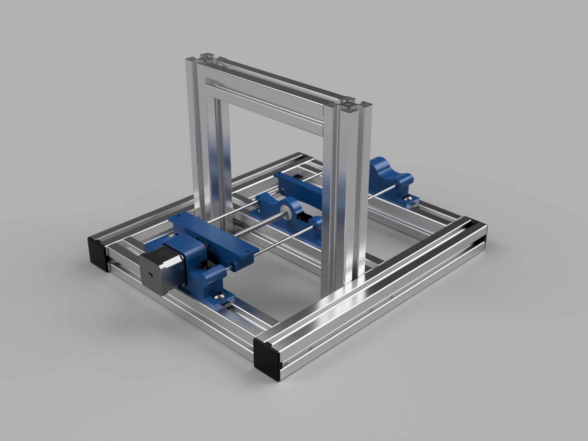
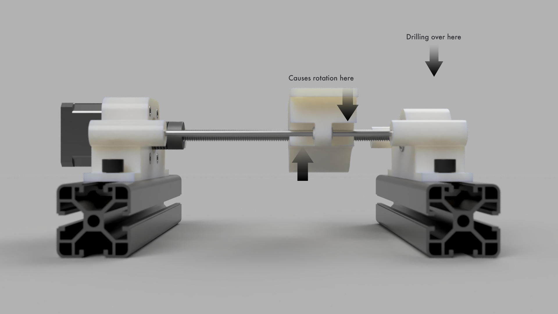
The lead screw saga

This issue was more annoying: the Y-lead screw was now too short. Completely my fault – this was 100% a design issue. At this point in the project I’d been riffing without CADing things first and didn’t realise that the position I had the anti-backlash nut lost 40mm of travel. Add another 20mm because of the spindle offset and I was 60mm out.

I discovered this by witnessing the anti backlash nut spring flying across the room as it spun off the edge of the screw.

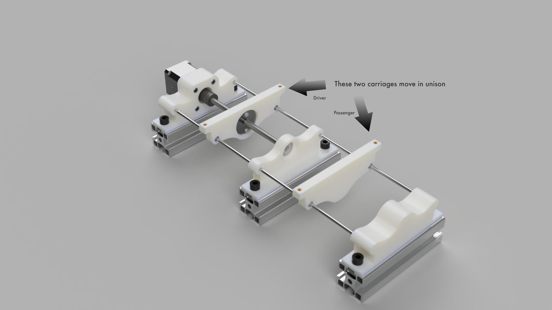
So I had a conundrum. One of the design goals of this project was to reuse as much if the Makibox as possible. I had already replaced all the 4mm linear rods with 12mm linear rail, leaving just the steppers, lead screws and controller board.

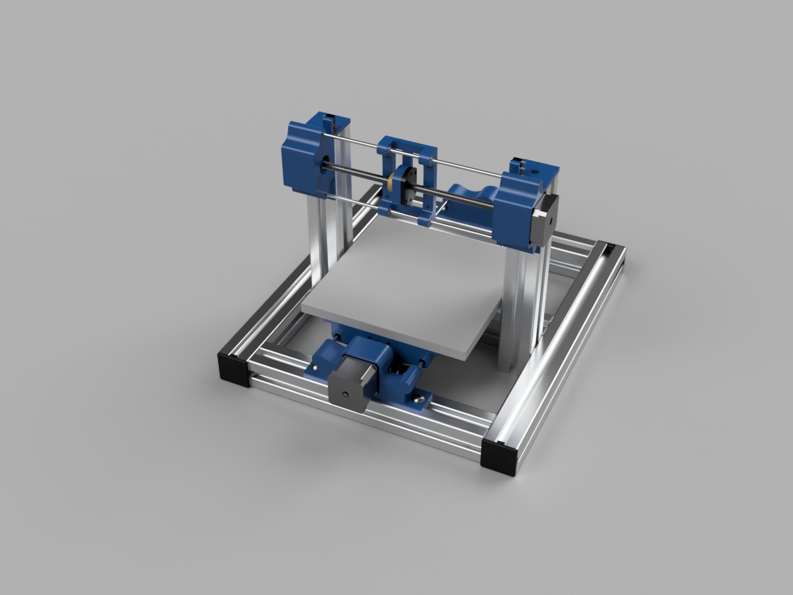
I could either redesign the y-axis, which would require a bunch of replacement parts, waiting for said parts and time; or I could just buy a longer lead screw.

I found a 300mm T8x8 on EBay in Australia for $30 delivered and it could arrive in three days. I did this.
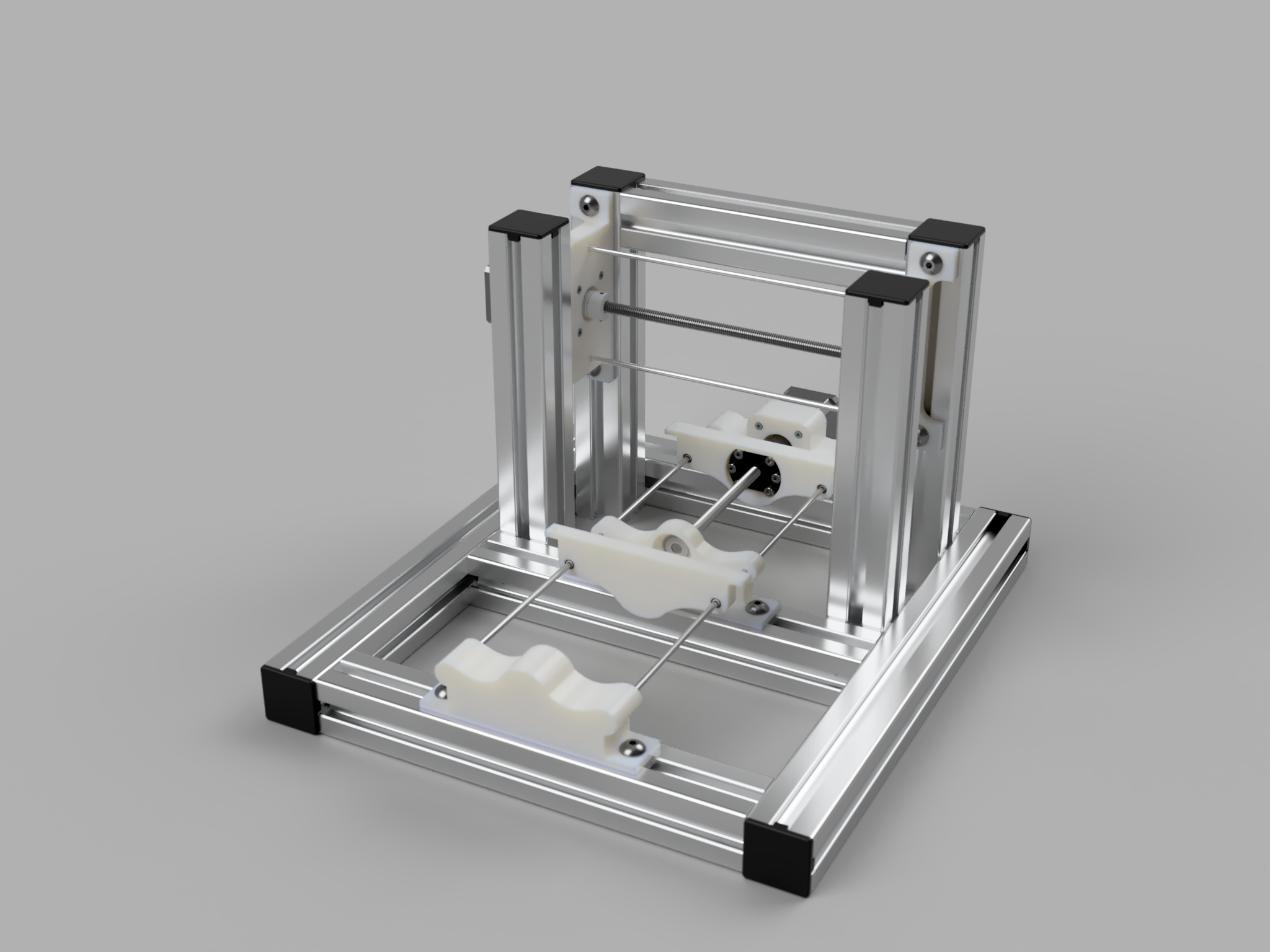
My homemade CNC mill’s completed X- and Y- Axes.

Alignment – Y axis

At this point I stripped everything back so I could align all the pieces.

I found a spare bathroom tile that I planned on using as a ground plane – it seemed flat enough for my purposes.

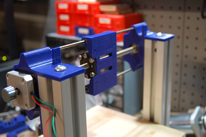
I started by squaring up the base frame using an engineer’s square.

Next a place one of the y-axis rails loosely in place using a 3D printed spacer. I dury rigged my depth gauge so I could dial it in – I got it to with in 0.05mm. Machinists would baulk at that but I’m fine with it.

I cheated a bit in the second rail: I simply put the bed on and rolled it up and down a few times to get alignment.

Finally I used the depth gauge to get the bed square.

Converting a Makibox into a PCB Mill – Reprogramming the control board

The version of the Makibox that I purchased came with a printrboard, however I fried that years ago. Makibox shipped me a replacement Print5D D8 controller.

I knew very little about this board, and I wondered how I was going to adapt it for CNC use.

I had some questions:

  1. How do I send it G-Code? Do I need to use the software that came with the Makibox?
  2. Controlling the three axes and endstops was easy, but how would I run the spindle?
  3. After more research about milling PCBs, I found out that using a bed levelling algorithm would give the best results – could the board do that?

After some googling, I found that a kind user had archived all of the original Makibox forums. A post about the D8 firmware lead me to the Makible bitbucket account, which not only housed the original firmware source, it also had the schematics!

Some more random googling yielded another interesting tidbit of information: Marlin has hardware definitions for the D8 board.

The original firmware (from 2014) was based on Sprinter which was forked and became Marlin.

Fun fact: Marlin is also what my Lulzbot Mini uses.

Sending G-Code

I know had an answer to question 1: Marlin appears as a serial device that you can simply send G-Code to. If you have screen installed on your *nix like computer you can just connect (by passing the path to your TTY device) and directly enter G-Codes – although using a G-Code sender is easier.

After wiring up the endstops and motors (only the X and Z because I’m still waiting on the slides for the Y) I entered G28 which runs the homing routine. It worked!

The next problem to solve was driving the spindle. The Makibox schematic revealed the drive circuit for both the hotbed and hotend use a MOSFET to switch a 24V line (using PWM). The MOSFET is rated to 40A, which is plenty to run the 5A spindle I have.

Welcome to 2018

This current firmware is ancient, is tuned to the Makibox build area and doesn’t support autolevelling or controlling a spindle, so I needed to upgrade to the latest Marlin. This was far easier than anticipated.

The board is based on the printrboard which is based on the teensy 2.0++, so the first step is to load the teensy board definitions into the Arduino IDE. Unfortunately, this isn’t via the usual method of adding a URL to the board manager – there is a installable which manually handles installation, and adds a bunch of wizards that, if you have done any Arduino development, kind of get in the way.

Regardless, it allowed me to choose the teensy 2.0+ as a build target.

Next, I modified the configuration.h and configuration_adv.h file with the new build area parameters, and set the various options. A number of these settings hadn’t changed since Sprinter, and I was able to just copy the values. I did have to modify a non-configuration file to allow pin 15 to be defined as a PWM pin.

After compiling, I put the board in bootloader mode by placing a jumper over the boot pins and clicking reset.

Once in bootloader mode I erased the EEPROM and uploaded the binary hex file via dfl-programmer.

sudo dfu-programmer at90usb1286 erase
sudo dfu-programmer at90usb1286 flash Marlin.hex

The spindle parameters took a little bit of trial and error to get right:

To calculate the SPEED_POWER_SLOPE use the formula:

(SPEED_POWER_MAX - SPEED_POWER_MIN) / 255

I decided to use 0%-100% as my MIN and MAX, so the value I needed was (100 – 0) / 255 = .392156863.

Using that range allows me to use different gear ratios and to drive a laser cutter without modifying the firmware.

I have purchased a copy of GWizard which calculates spindle speeds and feed rates, and it will output a power percentage based on the profile of the spindle, which makes the calculation easy.

Screenshot from GWizard

I’m not entirely sure what SPEED_POWER_INTERCEPT is, but I’d guess that it is a way of offsetting the speed. I’m not sure why you would need to do that.

The new firmware has given me the ability to set the spindle speed via M3, M4 and M5 (M3 and M4 do the same thing because the hardware can’t reverse the direction of the spindle), and in theory perform an auto-level – I say in theory, because I don’t have a levelling probe, nor do I have the Y-axis linear slides. I have now followed up with the AliExpress seller to see where they are.

So once again, I’m blocked – but progress has been made!

Converting a Makibox into a PCB Mill – Rebuilding the X-axis

In my previous post, I realised that the 4mm steel rods weren’t going to cut it when milling – they had way too much play, so I promptly ordered two 200mm linear rails (for the X-axis), two 400mm linear rails (for the Y-axis) and two 150mm 12mm linear rods and bearings (Z-axis).

The 200mm slides and the 150mm rods arrived promptly, but there was a delay on the 400mm slides. That, plus me needing a fair chunk of time to measure, drill and tap a bunch of holes meant I parked the project for a couple of weeks.

I finally managed to get a couple of days off while I changed jobs, so I arranged a hot date with my drill press.

The redesigned X axis, and Z-axis

The Tappening

The x-axis slide has four mounting screws which required tapped holes to be drilled into the two horizontal 4040 aluminium extrusions. Now, I’ve not done much in the way of metalwork since year 11 (some 18 years ago) and it took me ages to mark, drill and tap the holes. This was a good warm up for Z-axis face plate.

The face place required a total of 20 holes: four 2.5mm tapped to an M3 and sixteen 5.5mm counterbored to 10mm. It’s not the neatest job in the world, but it is functional. And I only misaligned one hole, which am actually amazed by.

I have stuck with 3D printed anti-backlash nut holders, with the intention of milling them out of aluminium once the mill is completed. This is why they are the shape they are – so they will be easy to mill.

The Z-axis

The same applies to the Z-axis end caps – I added grub screws to hold the linear rail which adds some rigidity – and they will be especially helpful on the milled version.

After doing a fit test it became clear that the motor couplers were too springy (the ones I bought are designed to deal with things being out of alignment) so I’ve now ordered some rigid ones that will eliminate any slop.

I 3D printed a Z-axis carriage to test fit, but it became clear it was too big (90mm tall) which meant my Z-axis would be less than my 70mm design goal. I’ve simplified it to be more box like (easier to mill down the track), and reduced the height to 60mm, by cutting down the flange on the anti-backlash nut, and by making it a two piece part. At this point, I calculate a 78mm of travel in the Z direction.

I now need to fabricate the aluminium face part part, which the carriage and the spindle screw in to.

Converting a Makibox into a PCB Mill – Building the X-axis

Re-designing the X-axis of my Makibox to PCB mill conversion has been a challenge in constraints. Due to an ordering mishap, and lack of engineering designs for the spindle I have been racking my brain to re-use the parts I have to create a workable X-axis.

The three constraints I have to work with:

  • The spindle can’t be too low – I want at least 70mm of vertical travel
  • The spindle can’t be too high – The further the cutting tool is from the centre of the holder, the more torque it needs to deal with
  • The spindle can’t be too far forward – I’d like the cutting tool to sit as close to the centre of the frame, so it can reach the full range of motion. The shaft of the spindle sits around 40mm from it’s mounting plate, which puts it out nearly 80mm when you include the Z-axis linear driver.

I looked at mounting the stepper motor on top of the vertical extrusion, but it failed constraint 3. It also gave me no where to mount the top steel rod. I toyed around with moving the steel rods but centred either side of the lead screw seems the best place for them.

I settled on a design where the motor hangs off the side of the vertical extrusion, with the steel rods mounted either side.

Render of the original PCB Mill X-Axis design

The test build

After printing motor and bearing holders, and the carriage I put everything together. I held the spindle against the carriage to get an idea of placement, and it became clear that the 4mm steel rods were going to flex too much under load.

Photograph of the PCB Mill X-Axis

They would be fine for a 3D printer or as a laser cutter, but even the small forces from a PCB mill bit would cause issues. It was time to replace the rods with something more robust.

I jumped on Aliexpress and found these 200mm linear guides that have a 12mm steel rod, and support for the full length, so bending should not be an issue.

I also decided to replace the Y-axis rods with the 400mm version of the linear guide. This will remove the flex in the bed and will make alignment easier (the three points of contact design I used was difficult to square).

While I was at it I ordered some linear bearings for the Z-axis for good measure.

A substantial redesign.

I have one 205mm cross bar, which a perfect support for one of the linear rails – I’ll need another one. I’ll also need another two, taller vertical extrusions to hold the cross bars. The two shorter vertical extrusions will hold the motor.

Here is a rough render without any joining hardware so you get the idea.

Render of the redesigned PCB Mill frame

I’ve had to move the vertical extrusions to the rear of the frame (which is fine, there are still two connection points there), giving the spindle plenty of room.

I’m going to design and print some new motor and bearing mounts for the X and Y axis. They will be much simpler as they no longer need to support the steel rods.

The rear support for the Z-axis will be 10mm aluminium, as I can get the supplier to cut it to the required 138mm length. The end caps – which act as a motor holder and rod support – will be plastic to start (I don’t have facilities to mill aluminium… yet). My intention is to mill replacements once the machine is complete.

Converting a Makibox – Building the Y-axis

I’ve now built the aluminium frame and completed the Y-axis. Of course, this was not without it’s problems.

Firstly, I misordered – I was one set of uprights short. This may not be a massive problem though, as I hadn’t taken into account the size of the spindle when designing the X-axis, and it wouldn’t have fitted in the configuration I had designed for – That’s what you get for forging ahead with out good engineering drawings.

Other minor issues were easily fixed by reprinting some parts – I added limit switches into the motor and bearing holders (though I haven’t worked out how to make the switch on the bearing holder work yet), I made the driver carriage wider so the whole anti-backlash nut fitted completely and I changed the shape of the passenger carriage so it could slide over the entire stroke.

A render of the new Y-Axis

Everything went together quite well – I did my best to square everything up, using a shim I printed – the holders may not be exactly in the middle, but they are all consistently out, which is the main thing.

I was a little concerned that both carriages were rotating around the z-axis, but realised that was because they weren’t joined yet, so there was only two points of contact, rather than four.

To fix that, I cut out a 205mm x 205mm MDF spoil board, and attached it using a 0.33mm feeler gauge squared it against one of the uprights.

I’m not sure I can do more alignment without having a X-axis, which requires a redesign.
See the video below for the test! (Excuse the upright video – I need to get an iPhone holder)

Converting a Makibox – Aluminium frame is done

I’m pretty happy with how the aluminium frame has come together. I’ve kept the X-axis pretty simple, though I tried a few iterations before coming to this shape.

Originally I had the vertical X-axis supports butted on the top of the horizontal Y axis base, but I was concerned with keeping the vertical… vertical. I could have used right angle brackets, but decided that by putting them in the inside of the base, I can add additional points of contact that would better support them. This configuration also gives a slightly larger base, so should make it slightly more stable. They are now attached in two dimensions which effectively works like a right-angle bracket.

The motor mount and bearing mounts are pretty simple, bridging the two verticals on each side. I toyed with running the bolts in a horizontal extrusion that would stop them from slipping down, but that would stop me from adjusting the heights when tramming.

On the topic of adjustments, I’m starting to regret the dual-carriage design, as there is an extra dimension that needs to be aligned – not only do I need to align the X, Y and Z axes, I need to make sure both slides are exactly parallel. I’ve bought a digital dial indicator which should help in squaring everything up – we’ll see how that goes.

I now have a complete bill of materials for the frame:

The order cost me just shy of $200, which already takes me over my $250 budget, but I’ve been reconsidering how much I’m spending, as I assumed I could use my Dremel 4300. After a bunch of reading, I think I’ll need to by a different spindle that has less runout.

Converting a Makibox – Designing the Y-Axis

I’ve been iterating the Y-axis in Fusion 360. A common design I have seen on other moving-bed designs is four linear bearings – one bearing at each corner of the bed. The problem with this design is you lose the distance between the bearings in travel. Since I have only have a maximum of 165mm on this axis, I didn’t want to lose too much to dead play.

Example of a moving bed with 4 bearings

Round 1 – Two Bearings

My first thought was use a single bearing on each side, introducing a minimum lost travel of 12mm (the width of the bearing). This looked like it would cause rotation problems, though – especially when dive cutting in the outer edges of the build area.​​​

Drilling on one side of the axis, causes excessive rotational forces at the bearing

Round 2 – Four Bearings

I went back and looked the parts I could salvage from the Makibox, and it turns out I have four 170mm linear rods at my disposal. This means I can create a passenger carriage – one that isn’t driven by the lead screw, but instead is pushed along it’s rails by the bed itself. This design gives four points of contact, eliminating the radial moment of the two bearing design (Note: this doesn’t deal with linear rod or bed flex, just the rotation issue). The disadvantage is the base is now double the size, but as the bed would have moved outside of the frame envelope during operations, it’s not that big of a deal.

Here is a render of the Y-axis. If you imagine a bed on top of it, attached to the two carriages – the left (driver) carriage is driven by the lead screw, while the right (passenger carriage is pushed by the bed. (I tried making a video, but the Fusion 360 animation workspace doesn’t support animating joints!)

Dual Y Axis Render

The Y-axis will have a 131mm travel – the loss is 7mm from the ball bearing, 7mm from the coupler and 20mm from the anti-backlash nut.

Issues

There are still a couple of side issues I still need to work out:

  1. ​The mount holes for the anti backlash nut are too close to the shaft, so I can’t heat fit brass inserts to screw in to – I may have to thread the plastic. I may be able to find some small nuts to secure it. Ideally once the mill is working I’ll be able to machine a bracket from a small plate of aluminium
  2. I have brass inserts in the carriages because I initially thought I would screw the bed down from the top – making replacement of the spoil board easier. This may not be an actual problem though – I’m not sure how often the spoil board needs changing. I may just make them screw holes, and be done with it. I have to think about it a bit more.

Next up: the X-axis

Turning a Makibox into a PCB Mill

You might remember the Makibox A6 – it was a sub-$400 3D printer that, like a lot of cheap printers at the time, was crowd-funded. It took forever to deliver, and there were a lot of problems with it.

The MakiBox A6LT

Personally, I managed to print a single cube on my first print. On my second print something went wrong and I blew up the control board. I suspect because of the stalled extruder motor. The extruder needed replacing, as did one of the plastic lead screws (that was my fault – I over tightened it).

In the process of trying to get the parts replaced, the delivery got lost – they claimed it had been delivered, but I hadn’t received yet. While trying to work this out, I had to quickly move interstate for work. To make matters worse, the company that made the Makibox disappeared around the same time, so I resolved myself to writing off the printer.

I decided to move to Melbourne permanently, so I flew back to Perth to collect my belongings – included what was left of the Makibox – and jammed it into my car for long drive over the Nullarbor.

And there is sat almost four years – dejected, in a cardboard box in my workshop.

On a recent trip back to Perth, my mother handed me a package which a person I worked with have given her. Apparently. it was delivered to the office years ago – so I had no idea what it was.

Low and behold, It was the replacement parts from my Makibox! Well, this was a sign. I put the parts next to the printer, as I wasn’t sure what I was going to do with it. I had an M3D printer which was pretty terrible – maybe I could frankenstein the two designs and get one printer out of them?

Fast forward a couple of months – I come in to a bit of spare cash after selling off my time tracking application, and I decide to bite the bullet and buy a real 3D printer – a Lulzbot Mini. After setting it up and kicking out a number of awesome prints, I placed the M3D next to the Makibox. I now had a collection of old, cheap and not very good printers. I had to do something about that.

Upcycling a Makibox

The Makibox has some decent steppers and screws in it (the M3D really doesn’t – half the problem really) so I started looking at the parts and wondering if I could convert it to a PCB mill. Ideally I’ll eventually want a proper mill that can do aluminium and stuff, but I reckon I can cobbled together something good enough to grind a few hundred micros of copper off some fibre glass. Bonus points if it’ll drill through holes.

What’s the worst that can happen? I have a broken Makibox?

Research

I’ve been doing some research into PCB mill designs over the past couple of weeks, and I’ve decided to go with a fixed gantry design (based heavily off the cheap Chinese machines). This means I only need three motors, and three lead screws.

I’m giving myself a $250 budget for the conversion.

Due to the existing hardware that I want to reuse, the actual build area for this machine will be relatively small, so I’m hoping that will help with the rigidity of the system (smaller builds should be stronger than larger ones). Given that this PCB mill gets decent results with a wood base, I’m feeling pretty confident we can get some good results with this.

Stocktake

  • 4 x NEMA 17 sized motors (Longs: 17HS 42BYGH 1.8°)
  • 1 x 218mm T8.8 (8mm diameter, 8mm travel per revolution) trapezoidal lead-screw
  • 1 x 165mm T8.8 trapezoidal lead-screw
  • 1 x 147mm T8.8 trapezoidal lead-screw
  • 2 x 226mm x 4mm steel rod
  • 1 x 170mm x 4mm steel rod
  • 1 x 164mm x 4mm steel rod
  • A bunch of cap hex screws
  • Plastic couplers
  • Plastic anti-backlash nuts

The plastic anti-backlash nuts are surprisingly good – I can’t detect any backlash (with the naked eye). The injected plastic piece has some thread that acts as a preloader – quite clever really. Regardless, I decided to order some metal anti-backlash nuts – I’m not sure how the plastic will hold up to the additional force of milling.

I also ordered some aluminium couplers (to replace the plastic ones), LM4UU linear bearings (to slide on the steel rods), and round bearings to hold the lead screws. Total cost so far: $79.68.

Everything else looks useable (at this stage) – I’m a bit concerned that the steel rods aren’t straight enough, but I’ll run with them for the moment.

I’m going with 4040 aluminium t-slot for the frame. I’ve found a Melbourne based supplier so I should be able to get high-quality stock quickly (and cut to size!). But before I order them, I’m going to design the mill in Fusion 360 so I can test for fit and size.

You can see the render of the Y-axis here:

Render of the Y-Axis

The X-axis will be a (wider) copy, rotated 90 degrees. The Z-axis will still need some thinking.

I will print the motor bracket, bed and bearing holder on my Lulzbot Mini. This is is the cause of the weird design – it needs to fit in the 150mm x 150mm build envelope of the 3D printer.

Based on the dimensions from Fusion 360 the design should allow a Y-axis travel of around 168mm 156mm (Update: I didn’t take in to account the linear bearing width). I still have to work out the X-axis travel.