Turning a Makibox into a PCB Mill
You might remember the Makibox A6 – it was a sub-$400 3D printer that, like a lot of cheap printers at the time, was crowd-funded. It took forever to deliver, and there were a lot of problems with it.
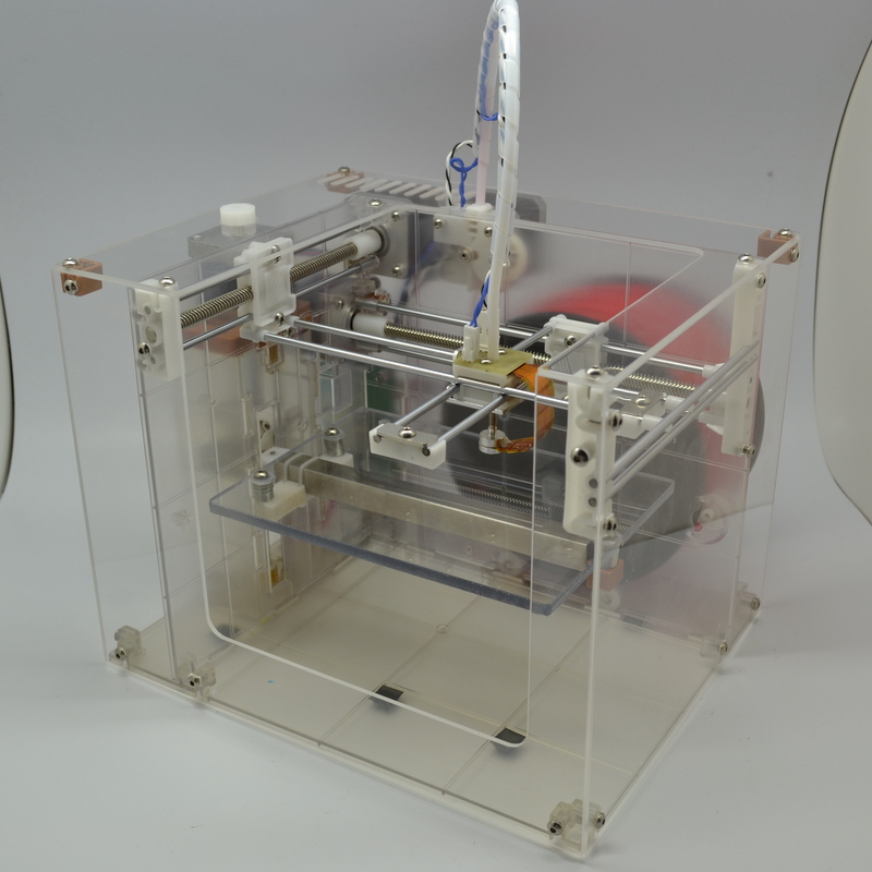
Personally, I managed to print a single cube on my first print. On my second print something went wrong and I blew up the control board. I suspect because of the stalled extruder motor. The extruder needed replacing, as did one of the plastic lead screws (that was my fault – I over tightened it).
In the process of trying to get the parts replaced, the delivery got lost – they claimed it had been delivered, but I hadn’t received yet. While trying to work this out, I had to quickly move interstate for work. To make matters worse, the company that made the Makibox disappeared around the same time, so I resolved myself to writing off the printer.
I decided to move to Melbourne permanently, so I flew back to Perth to collect my belongings – included what was left of the Makibox – and jammed it into my car for long drive over the Nullarbor.
And there is sat almost four years – dejected, in a cardboard box in my workshop.
On a recent trip back to Perth, my mother handed me a package which a person I worked with have given her. Apparently. it was delivered to the office years ago – so I had no idea what it was.
Low and behold, It was the replacement parts from my Makibox! Well, this was a sign. I put the parts next to the printer, as I wasn’t sure what I was going to do with it. I had an M3D printer which was pretty terrible – maybe I could frankenstein the two designs and get one printer out of them?
Fast forward a couple of months – I come in to a bit of spare cash after selling off my time tracking application, and I decide to bite the bullet and buy a real 3D printer – a Lulzbot Mini. After setting it up and kicking out a number of awesome prints, I placed the M3D next to the Makibox. I now had a collection of old, cheap and not very good printers. I had to do something about that.
Upcycling a Makibox
The Makibox has some decent steppers and screws in it (the M3D really doesn’t – half the problem really) so I started looking at the parts and wondering if I could convert it to a PCB mill. Ideally I’ll eventually want a proper mill that can do aluminium and stuff, but I reckon I can cobbled together something good enough to grind a few hundred micros of copper off some fibre glass. Bonus points if it’ll drill through holes.
What’s the worst that can happen? I have a broken Makibox?
Research
I’ve been doing some research into PCB mill designs over the past couple of weeks, and I’ve decided to go with a fixed gantry design (based heavily off the cheap Chinese machines). This means I only need three motors, and three lead screws.
I’m giving myself a $250 budget for the conversion.
Due to the existing hardware that I want to reuse, the actual build area for this machine will be relatively small, so I’m hoping that will help with the rigidity of the system (smaller builds should be stronger than larger ones). Given that this PCB mill gets decent results with a wood base, I’m feeling pretty confident we can get some good results with this.
Stocktake
- 4 x NEMA 17 sized motors (Longs: 17HS 42BYGH 1.8°)
- 1 x 218mm T8.8 (8mm diameter, 8mm travel per revolution) trapezoidal lead-screw
- 1 x 165mm T8.8 trapezoidal lead-screw
- 1 x 147mm T8.8 trapezoidal lead-screw
- 2 x 226mm x 4mm steel rod
- 1 x 170mm x 4mm steel rod
- 1 x 164mm x 4mm steel rod
- A bunch of cap hex screws
- Plastic couplers
- Plastic anti-backlash nuts
The plastic anti-backlash nuts are surprisingly good – I can’t detect any backlash (with the naked eye). The injected plastic piece has some thread that acts as a preloader – quite clever really. Regardless, I decided to order some metal anti-backlash nuts – I’m not sure how the plastic will hold up to the additional force of milling.
I also ordered some aluminium couplers (to replace the plastic ones), LM4UU linear bearings (to slide on the steel rods), and round bearings to hold the lead screws. Total cost so far: $79.68.
Everything else looks useable (at this stage) – I’m a bit concerned that the steel rods aren’t straight enough, but I’ll run with them for the moment.
I’m going with 4040 aluminium t-slot for the frame. I’ve found a Melbourne based supplier so I should be able to get high-quality stock quickly (and cut to size!). But before I order them, I’m going to design the mill in Fusion 360 so I can test for fit and size.
You can see the render of the Y-axis here:
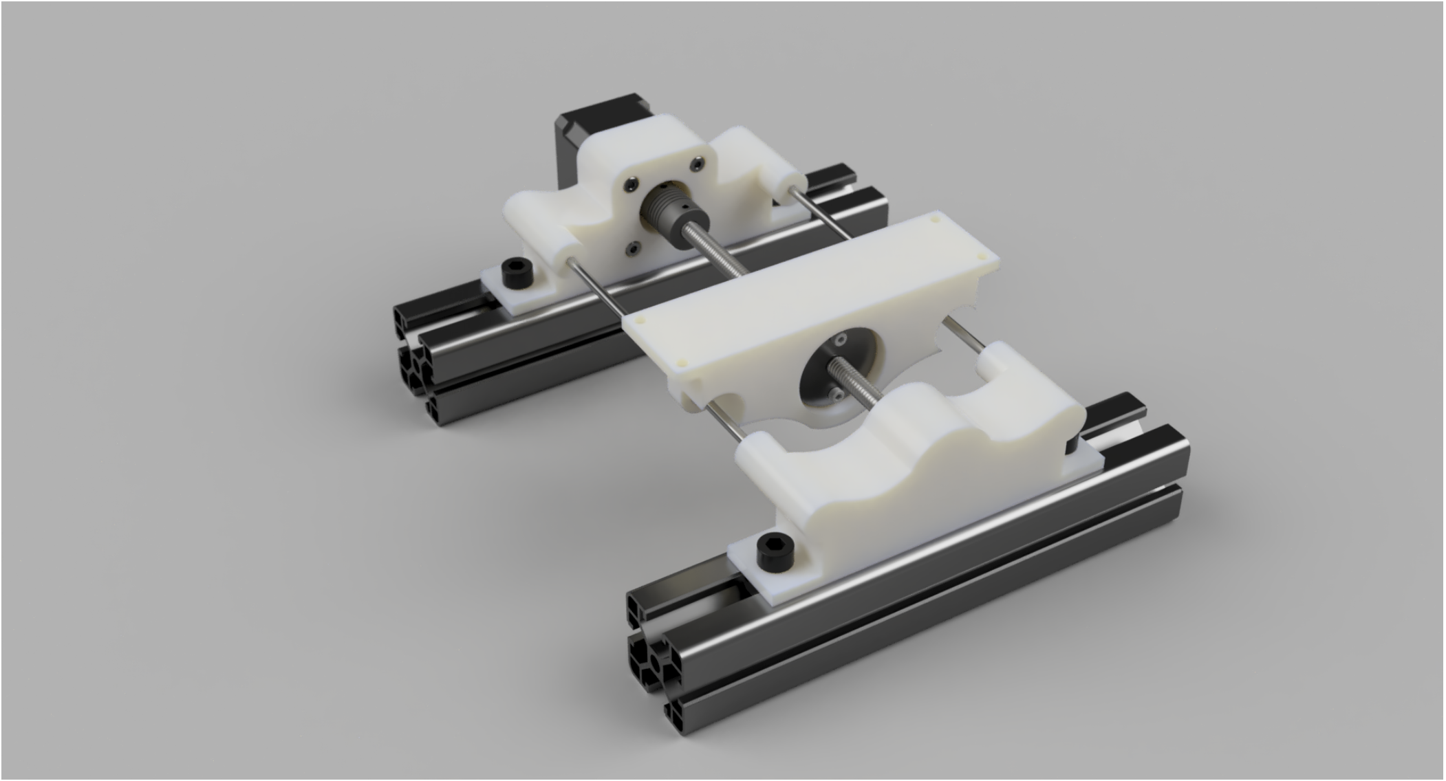
The X-axis will be a (wider) copy, rotated 90 degrees. The Z-axis will still need some thinking.
I will print the motor bracket, bed and bearing holder on my Lulzbot Mini. This is is the cause of the weird design – it needs to fit in the 150mm x 150mm build envelope of the 3D printer.
Based on the dimensions from Fusion 360 the design should allow a Y-axis travel of around 168mm 156mm (Update: I didn’t take in to account the linear bearing width). I still have to work out the X-axis travel.