@madpilot makes

IKEA hacks: A microwave interface for the Duktig kids kitchen

The finished product

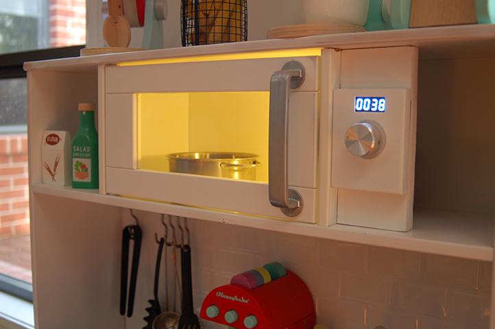
Hugo just turned one, and to celebrate we bought him a Duktig kitchen from IKEA. Like everyone else we painted and added fake subway tiles, but I wanted to take it a bit further and add a working microwave panel.

Hugo is obsessed with pressing buttons and turning knobs – We were staying at an AirBNB recently that had a microwave that you controlled using one big knob and he loved it – so I thought I would model that.

I ordered a 4-digit 7 segment display, a rotary encoder and an aluminium knob, which I planned to run off an Arduino Nano.

Rotary Encoders

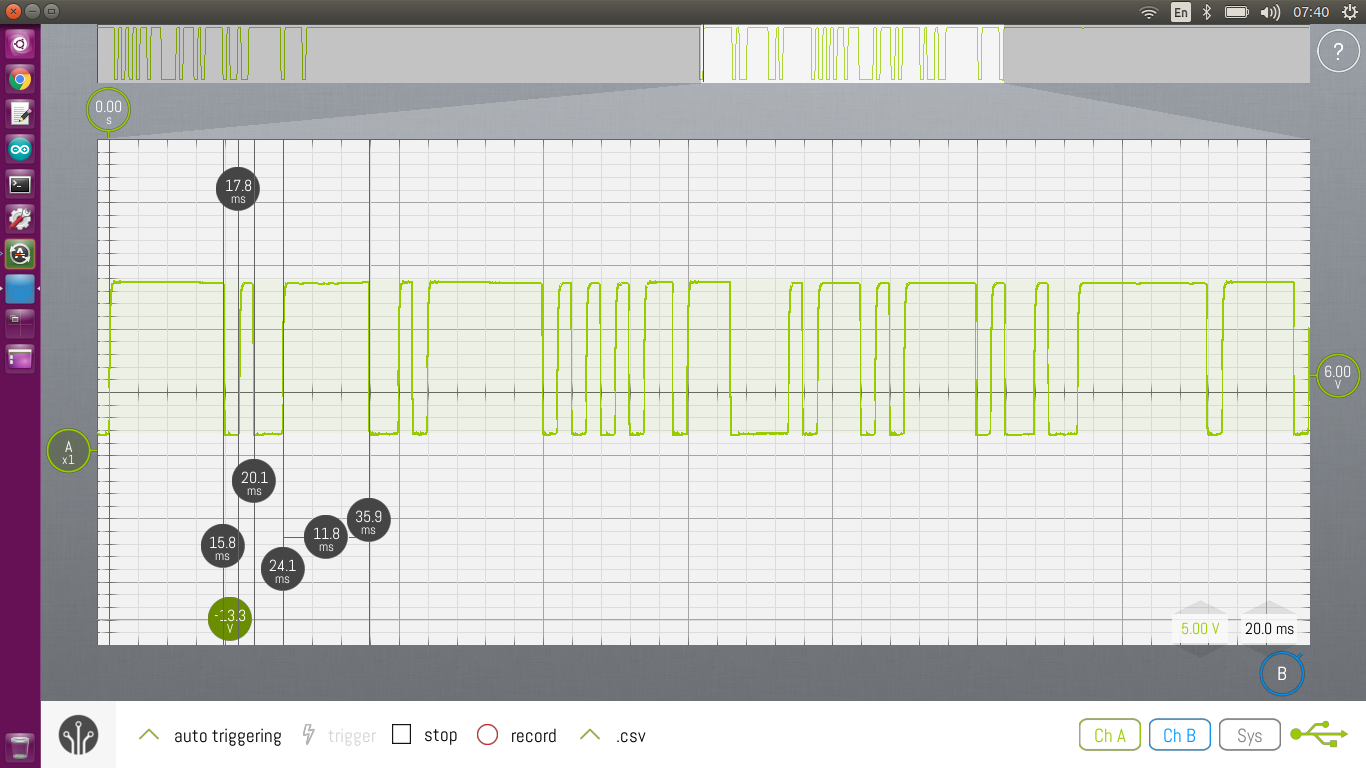
A rotary encoder looks a lot like a potentiometer, however they work quite differently. For starters, there is no limiter so they rotate through a full 360 degrees.

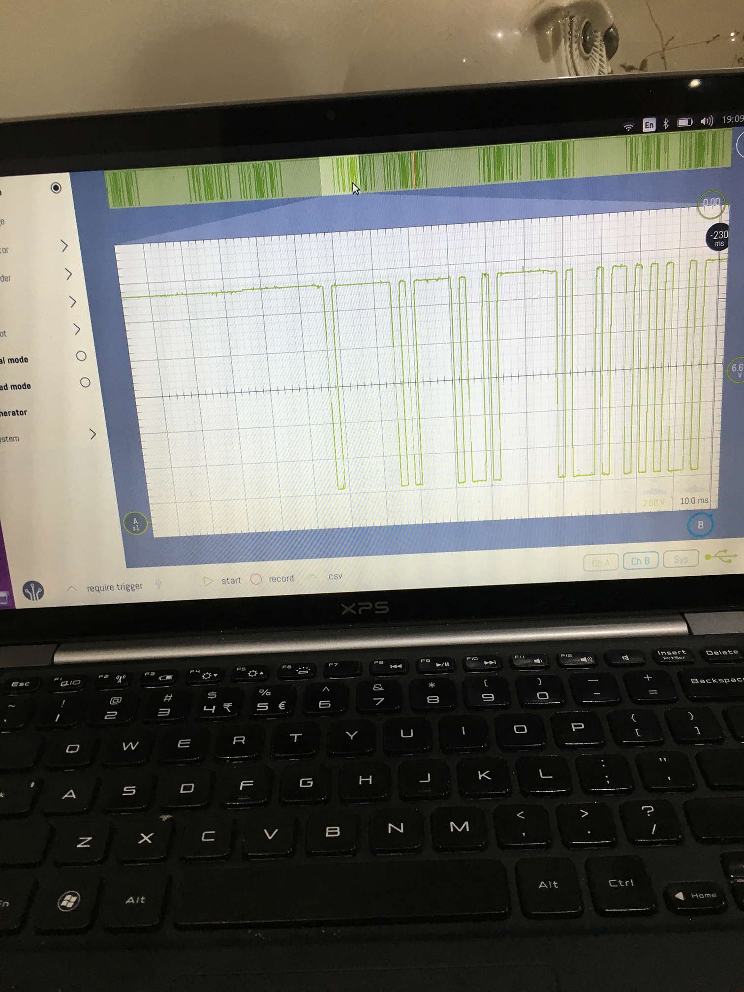
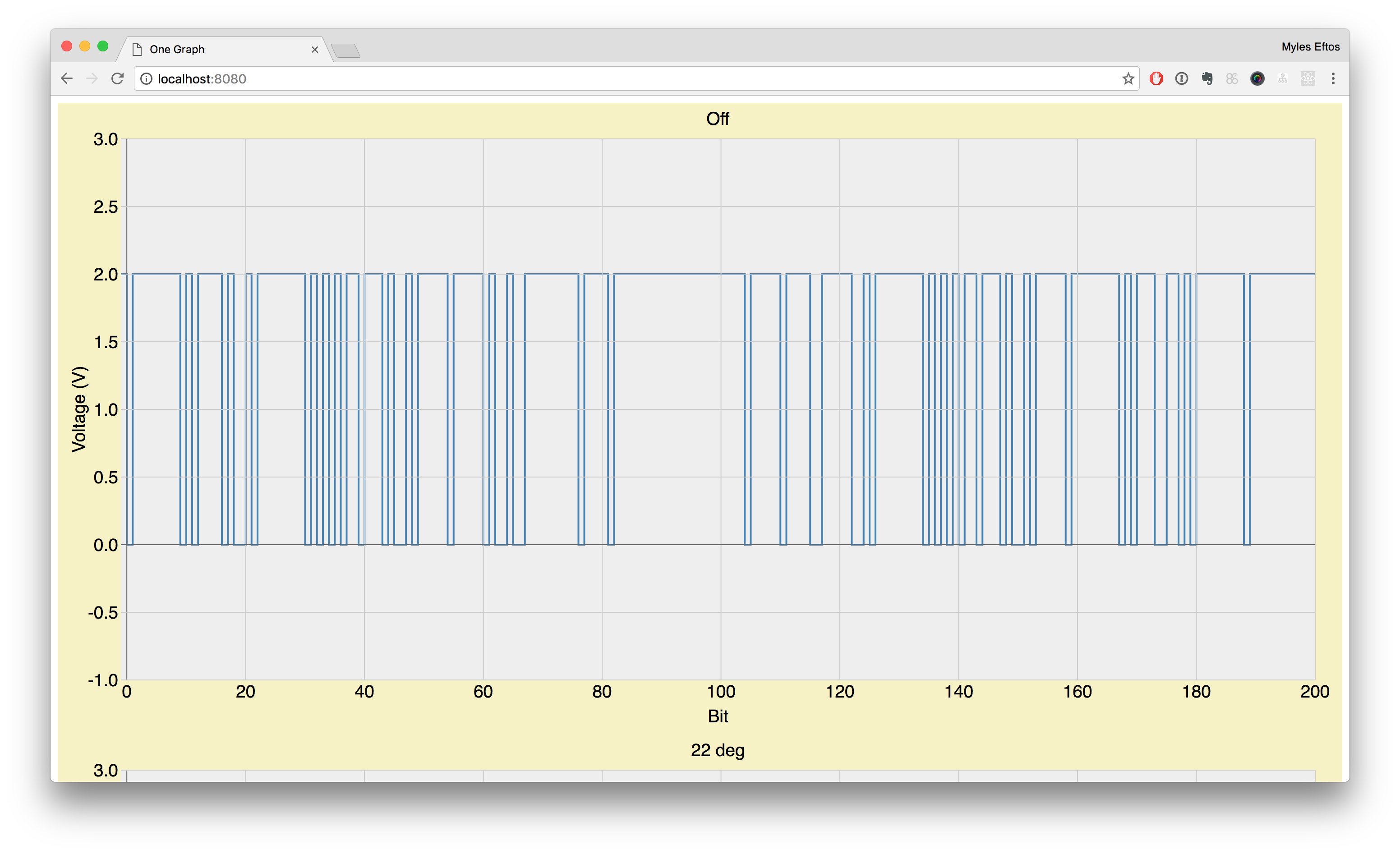
But the main difference is how you interface with them: they output a digital code called a Gray code. Named after Frank Gray, it ensures that one-bit only ever changes at one time so we can be sure of the direction the shaft turns.

Of course, the library we are using hides this from us, so all we care about is the value that comes back.

The encoder I’m using also has a push button, which I’ll use to start and stop the timer. The library also abstracts this.

The display

The four-digit seven-segment display has a built in driver chip that means we only need two pins to drive it: a clock and data. Again, there is a convenient library that deals with pushing data to the board.

Buld progress

The LEDs

I had six yellow LEDs that I pulled out of the night light I gutted to make an interim night light, so I repurposed them for this project. As the draw a total of about 120mA when on, they can’t be driven by the Arduino directly – I’m using a BC547 transistor to drive them.

The speaker

I added a cheap, 8 ohm streaker than I’m driving directly off one of the Arduino digital outputs. There is a tone library that turns a GPIO on and off quickly enough to create a tone. I maybe regretting this already though – it can get quite annoying.

Sleeping

This microwave controller needs to be battery operated. To do that without costing me a small fortune in batteries, the controller needs to turn itself off. Luckily, the Arduino Nano supports a deep sleep which reduces it’s current draw. The Nano can then be woken up by a pulse on either pin 2 or pin 3.

By feeding the signal from the rotary encoder and the switch into those pins, any rotation of button pressing will wake up the processor.

There is a slight problem though: there are two pins on the rotary encoder, and one on the switch: we need another input.

Or do we?

Rotary encoders have a physical “click” (called a segment). On the particular encoder I have, each click goes through a complete Gray code cycle, meaning there is a guaranteed two logic level transitions on each pin per segment. And, if you have ever watched a small child spin a knob, you would have noticed that their developing fine motor skills result in big rotations. In this case I can happily take the output of one of the encoder pins, and be confident that it will always wake.

So, the switch is wired to GPIO 2, encoder pin A is wired to GPIO 3 and pin B is wired to GPIO 4.

The Controller Schematic

The code

There are four main parts of the code: reading the encoder, the display code, the code that puts the MCU to sleep, and the interupt handler that wakes it back up again.

Most of the heavy lifting for interfacing with the encoder and display is done by two libraries.

The encoder library uses polling rather than hardware interrupts (which is good because I would have run out of interruptible pins). Every millisecond it checks the state of the encoder, and can work out if it has been spun or not. This library exposes the delta, we we use to increment or decrement the display.

The library also provides a callback that is fired on button clicks. Each clock toggles the running variable and the returns control back to the loop.

The display library at it’s lower levels takes four bytes – one for each number. Each bit of each byte represents a segment of the display. Thankfully there are some helper methods to display common things like numbers.

You can download the code on Github.

The loop

Because all of the inputs are handled via interupts, the loop just needs to deal with updating the display.

The left variable represents the number of seconds remaining. The first thing to do is adjust it if the encoder changed. We simply add the delta to it. Note that his happens regardless of whether the timer is running or not – this means you can add or remove time even when the microwave is running.

If the timer is running and the LED is off, I turn it on (and vis-e-versa).

If the timer is running the variable automatically gets decremented every 1000 milliseconds.

If the variable is 0, the timer stops and I display the word end and sound the beeper. (The LEDs will also go off)

The display routine gets called every 500ms. Why every half second? So we can flash the dot to show that the timer is running!
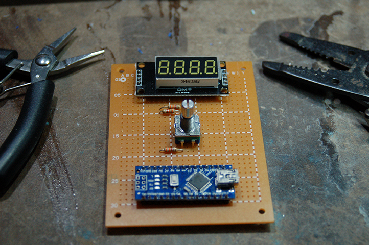
The build

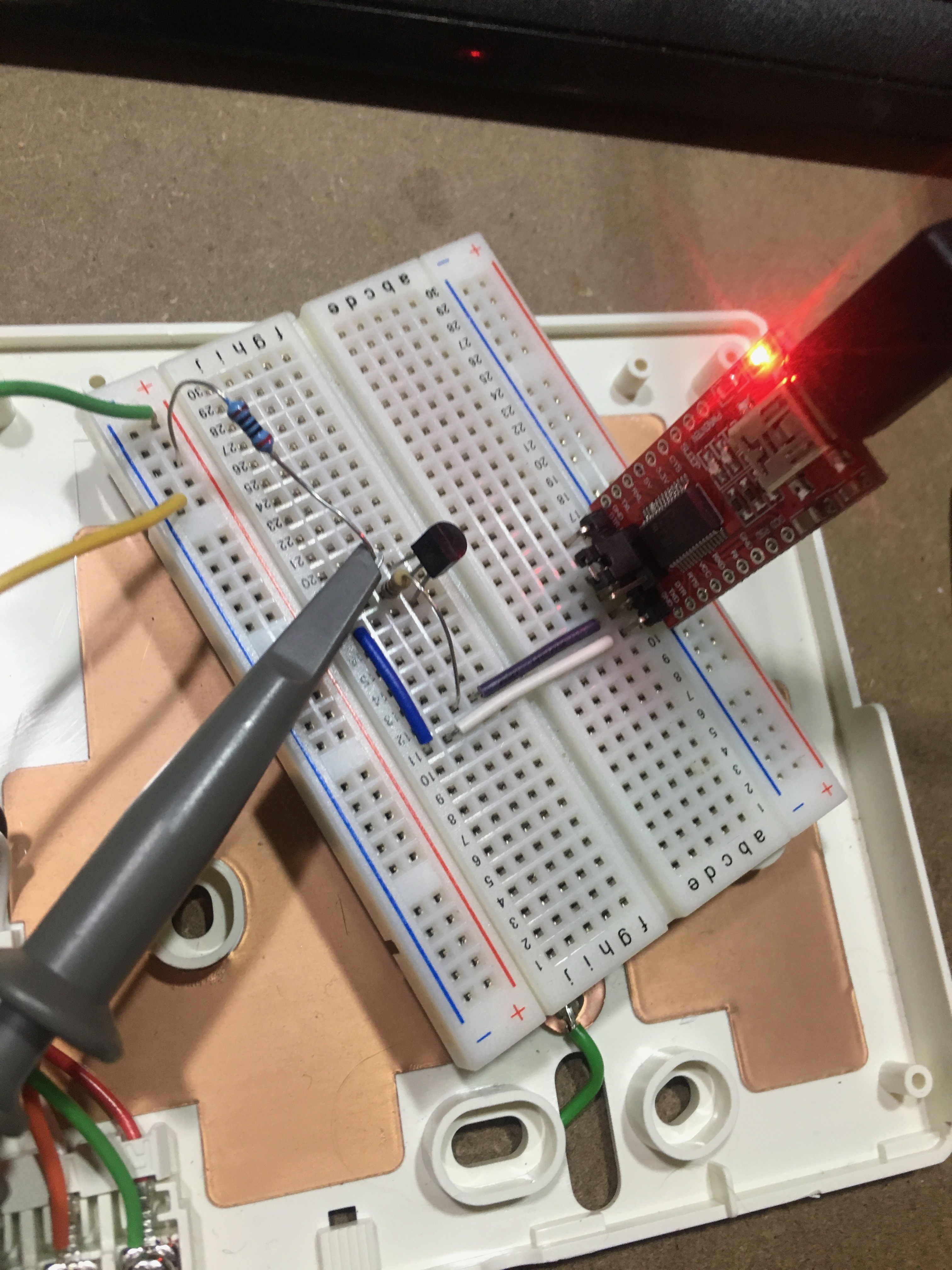
I was hoping this would be a quick weekend project, so I threw the circuit together using perf board. Of course everything always takes longer than you expect, but it kind of worked out well, because the perf board made the feature creep easier to deal with.

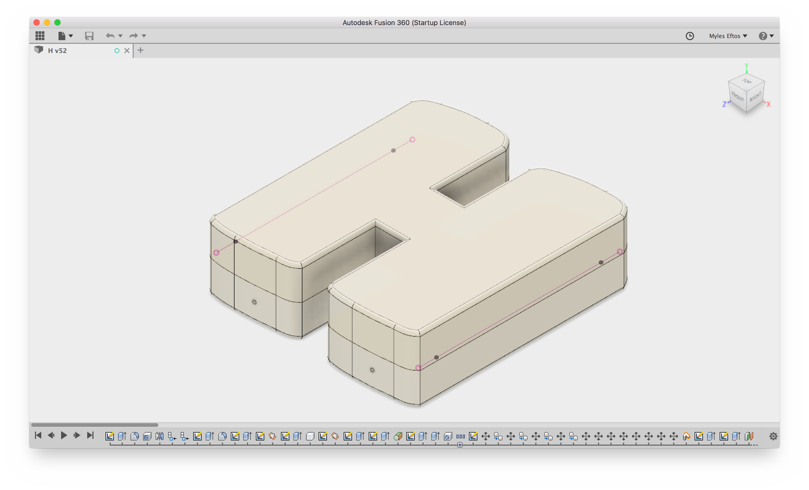
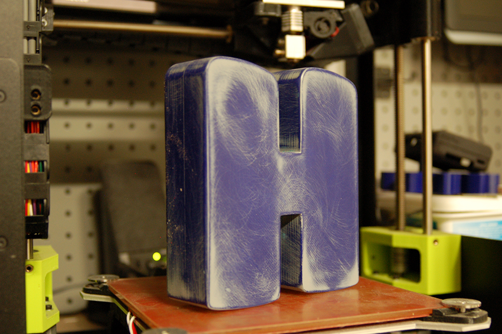
I 3D printed a “case” though my printer’s build area was too small to cover the whole area, so I made an MDF backing plate. Pro tip: don’t use pin to mark construction lines: paint won’t stick to it. Also: prime MDF – it absorbs paint like no body’s business. What should have been two coats required four.

Power

During testing I realised that there were LEDs on both the Arduino and the display that stayed on regardless of whether the Arduino was asleep or not. I measure the power draw whilst sleeping at it was sitting at about 15mA. A AA battery has a capacity of around 2400mAH, so a set would last around 160 hours or 6 days.

Clearly that is too high.

I removed the LEDs and that brought the draw down to 2mA, which buys me 1200 hours or 50 days. Better, but not amazing. Unfortunately, the Nano isn’t great as a lower power device. If I could be bothered removing the chip from the perf board, I could remove the FTDI drive and power regulator and probably claw back a bit of quiescent current.

I have ordered a boost converter so I can run the board off two batteries at 95% efficiency rather than the four at the moment so I might just use a couple of C cells which have 8,000 mAH capacity (nearly half a year).

See the microwave in action!

Hugo’s Nightlight: Modelling and Printing the Mold Master

Initially I thought about mounting the electronics in the back of the H, trying to fit everything in the footprint of the mold. But if I could get lights on the back, there would be some cool effects I could achieve. To get a consistent glow, the LEDs would need to be wedged in the middle of the H.

This did make mounting the PCB difficult though. I decided that I would mount the H on a small plyth that would house the electronics.

Autodesk Fusion 360 can extrude type, so all I needed to do was pick my type face. I wanted something childlike (not Comic Sans) so I went with Titan One.

Next, shelled, then mirrored to form the two halves. I added some alignment holes, to make gluing easier and finally created some nubs that will act as anchors for the plyth. The nubs were printed as separate parts so I didn’t need to print supports.

Printing

Each of the two halves took around 2 hours to print. Of course, because of how FDM printing works, the result was pretty streaky. The silicon I had literally talks about how fine detail it is, so I would need to do something about the streaks.

My dad used to make scale model aeroplanes, and I always remember him filling the joints with wood putty and then sanding to get a smooth finish, so I thought I would try that.

It turns out the gaps were just too big, and using a water based putty while wet and dry sanding meant the putty would come off.

Next I tried an auto sealer that was supposedly sandable. This didn’t work either because it was too rubbery.

At this point I spent AGES wet and dry sanding, starting at 80-grit and worked my way up to 240 before I found out about auto primer/filler.

This stuff is designed to cover up small scratches in car body work, and is sandable, allowing you to get a really smooth finish.

I did two coats, and sanded with wet and dry, 400 grit, and then a final coat before finishing with an 800 grit. It worked really well. It also saved a lot of time – sanding to a smooth finish is hard.

Hugo’s Nightlight: Part I

Long before Hugo was born, I had hatched a plan to build him a nightlight. Originally inspired by this, I decided to go for something less fragile – a simple H with some RGB LEDs.

Just before Hugo was born, I added a LIFX bulb to our bed side table, and added some Flic buttons that gave us better control on the lights. Using a Node Red flow, I setup the light to go to 5% brightness on a single click, 20% on a double click and a 2 second hold set the light to 100%. This worked really well: if we wanted to check on the baby, we could just single click, and get enough light to see him without waking him.

The downside was if the Flics stopped working we needed to use our phones, so the second requirement was a hardware switch to turn the light on and off. It should have configurable single, double and hold actions.

After Hugo moved to his own room, I wired up the same LIFX and Flic setup, adding a slow fade to the lights, so as to not startle the little fella when the lights switched on or off. I wanted the night light to do the same, so it would need some sort of tweening library.

Finally, a mate of mine was telling me about his kids grow light that turns on in the morning to let the child know that it’s time to wake up. I thought it would be kind of fun to have a cute sun rising animation. I thought about adding an alarm feature in to the light, but decided that I can do that using home assistant and node red, which saved me adding a Real-time clock and having to deal with times and other such nonsense.

Giving these requirements I went and ordered a tape of WS2812B LEDS from AliExpress ($12 for 100!) and got to work.

Making a plastic H

I needed a translucent H. My first thought was to try the usual places to see if there was something I could buy off the shelf. There was a few places that sold acrylic signs that would have been suitable, but they weren’t quite what I was looking for. I really wanted a completely milky white H with the LEDs embedded in the middle.

Well, I have a 3D printed, could I do something with that? I went in a hunt for translucent white filament. It turns out (for reasons I will discover later) that isn’t a thing. Odd.

I picked up some light blue translucent filament and did a small test print, but the print came out really streaky. Not what I wanted.

Then I remembered reading about resin casting. What if I could print a master, cast a mold in silicon, then cast the whole thing in resin? A quick Google for some tutorials and it sees plausible – in fact a bunch of people embed LEDs for cos play jewellery.

The problem is, all the examples I see are clear. You can get pigments to embed in the resin, but a white translucent one alludes me. Hmmm.

At this point I decided to go in to the local Barnes (a store that specialised in casting and other craft stuff) and had a chat with the staff. Apparently white translucent is really hard. The lady I spoke to thought that I might be able to get the effect I want by using a really small amount of pigment. Like, really small (she says that fully opaque happens at about 2%).

I buy a starter pack which has the 500mL of pink silicon, 500mL of resin and a bunch of measuring cups, containers and stirrers. I also bought some modelling clay and some spray on wax as I needed to make a two part mold. Unfortunately, this stuff ain’t cheap – all up it cost me $150.

Next step: Make the master.

Hacking a Cheap Wifi Outlet

DISCLAIMER: This project plugs in to the mains, which has dangerous voltages and can kill you. Never plug in the device working on this project – you can re-program using an external 5V supply wired up to the same pads that the red and black wires connect to (CONN1).

I have a Rancilio Silvia coffee machine, that needs time to warm up correctly in the morning – 30 minutes gets everything up to temperature, allowing me to draw excellent coffee shots.

For the past couple of years, I run a simple mechanical timer that turns on at 6am, and goes off at 8am which is fine for the days I go to work, but if I work from home, or it’s the weekend, I’m left with a cold coffee machine unless I turn it to manual mode – which often results in me forgetting to turn it off!

To get around this, I’d been planning on getting a smart switch which would integrate with my Home Assistant setup. I looked at the Belkin Wemo, but it seems a little expensive at $80 a pop.

I thought about designing and building my own one, but the prospect of messing around with mains power didn’t excite me, nor did 3D-printing a case – 3D printing plastic, by definition isn’t very fire resistant.

Browsing at least looked the same for $AU20 delivered. Even if it wasn’t ESP8266, I could probably gut it and insert a custom board, so I ordered one.

It arrived pretty quickly.

I promptly pulled it apart. There was a daughter board that looked suspiciously like a ESP8266 although the footprint wasn’t the same as any reference design I could find.

So, I pulled the little metal shield off, and low-and-behold! An ESP8266! Now that I knew we were in business, I installed the iPhone application that comes with it, to try and work out how it was wired up.

The device

This particular switch has an obnoxious blue LED that is used to indicate power, and network connection (it flashes when not connected). It also has a red LED that is on when the relay is turned on. Finally, there is a button that allows you to turn the relay on and off manually.

Pins

A quick google, and I found the pin out of the ESP8266 chip – now it was just a matter of tracing the wiring back to each LED and the switch. I also needed to find where the TX, RX, Reset and GPIO0 were so I could program it.

Here is what I found:

  • GPIO 4 is the Blue LED
  • GPIO 5 is both the Red LED and the Relay
  • GPIO 13 is the button

I’ve marked the TX, RX, Reset and GPIO0 pins on the above image. By wiring these pins up to a FTDI cable, I was able to reprogram the switch, thus freeing me from the shackles of the crappy iOS app, and allowing my home-assistant.io server to talk to the switch.

Now, thanks to a Home Assistant and a NodeRed flow, the coffee machine will turn on between 6:30am and 1pm everyday UNLESS it detects that I’m not home. Nice!

You can see the code that I use (It’s based heavily on my garage door opener project).

If that code is too complicated, I’ve uploaded some example code that will turn the switch into a simple web server.

  1. Create a new Arduino project
  2. Insert the code
  3. Compile and upload
  4. Point your browser at http://esp8266.local/on to switch on and http://eso8266.local/off to switch off

Garage Door Opener – Modifying the ESP8266 Over-the-Air update code

Now that I have the proof of concept code running, it’s time to modify the built in Arduino core library that handles OTA updates.

The existing OTA library takes a binary object and an optional MD5 hash (to verify the upload), stores it in flash memory, then swaps the old binary out of the new binary and reboots the device.

To do verification via digital signatures, we need three additional pieces of information: the developers certificate (used to decrypt the hash), the encrypted hash, and the Certificate Authority certificate used to verify the developers signature.

The CA needs to be compiled in to the source code – there is little point sending that along with our payload.

The developer certificate and encrypted hash on the other hand, need to be supplied with the binary . One option is to upload the three files separately, but this would require extensive reworking of the updater API, and of the OTA libraries.

A better option would be to somehow bundle all three files in one package, which is the path I am looking to go down.

So, the first thing to do is work out what the file format looks like.

The binary blob is of an arbitrary size, and starts with the magic byte: 0xE9, which I assume is an instruction that is required to start the boot process.

Our certificate is also an arbitrary size. The signature will be fixed size, but dependent on the algorithm we use. Clearly we need some way of instructing the updater code where the boundaries for each file are.

We could pack them at the beginning, and set the byte before the file with the expected length – ie if our signature was four bytes, and certificate was 6 bytes it might look like this:

[ 4 | s | s | s | s | 6 | c | c | c | c | c | c | … ]

but that would mean we’d have to move the data around, as the bootloader would be looking for the magic number in the position 0. I’ve decided to do it the other way around – I’m going to use the last two bits to signify the lengths, and then count backwards. ie:

[ … | c | c | c | c | c | c | s | s | s | s | 6 | 4 ]

I wrote a quick little c program that packages everything up.

#include <stdio.h>
#include <stdlib.h>

unsigned char *bundle;

uint32_t size;
uint32_t certificate_size;
uint32_t signature_size;

int main() {
  FILE *f1 = fopen("WebUpdater.ino.bin", "rb");
  if(f1) {
    fseek(f1, 0, SEEK_END);
    size = ftell(f1);
    rewind(f1);
    printf("Binary file size: %i\n", size);
  } else {
    printf("Unable to open WebUpdater.ino.bin\n");
    return -1;
  }

  FILE *f2 = fopen("developer.crt.der", "rb");
  if(f2) {
    fseek(f2, 0, SEEK_END);
    certificate_size = ftell(f2);
    rewind(f2);
    printf("Certificate size: %i\n", certificate_size);
  } else {
    printf("Unable to open developer.crt.der\n");
    return -1;
  }

  FILE *f3 = fopen("WebUpdater.ino.sig", "rb");
  if(f3) {
    fseek(f3, 0, SEEK_END);
    signature_size = ftell(f3);
    rewind(f3);
    printf("Signature size: %i\n", signature_size);
  } else {
    printf("Unable to open WebUpdater.ino.sig\n");
    return -1;
  }

  printf("Signature size: 0x%x\n", signature_size);
  uint32_t bundle_size = size + certificate_size + signature_size + (2 * sizeof(uint32_t));
  bundle = (unsigned char *)malloc(bundle_size);

  for(int i = 0; i < bundle_size; i++) {
    bundle[i] = 0;
  }

  fread(bundle, size, 1, f1);
  fread(bundle + size, certificate_size, 1, f2);
  fread(bundle + size + certificate_size, signature_size, 1, f3);

  bundle[bundle_size - 4] = signature_size & 0xFF;
  bundle[bundle_size - 3] = (signature_size >> 8) & 0xFF;
  bundle[bundle_size - 2] = (signature_size >> 16) & 0xFF;
  bundle[bundle_size - 1] = (signature_size >> 24) & 0xFF;

  bundle[bundle_size - 8] = certificate_size & 0xFF;
  bundle[bundle_size - 7] = (certificate_size >> 8) & 0xFF;
  bundle[bundle_size - 6] = (certificate_size >> 16) & 0xFF;
  bundle[bundle_size - 5] = (certificate_size >> 24) & 0xFF;

  FILE *f4 = fopen("Bundle.bin", "wb");
  if(f4) {
    fwrite(bundle, bundle_size, 1, f4);
    printf("Bundle size: %i\n", bundle_size);
  } else {
    printf("Unable to save Bundle.bin");
  }

  return 0;
}

This produces a Bundle.bin file that can be uploaded.So far, I’ve managed to decode the lengths, and find where the two files I’m interested are live. Next I need to pull the files out, and do the verification. I think I’ll sign the binary using MD5 for the moment, as the updater class already has that function built in, so I effectively get it for free.

Garage Door Opener – Signing a binary using axTLS

Comparing the SHA256 of a file after it has been uploaded allows us to check that it hasn’t changed. This doesn’t tell us if the file has been tampered with though – it would be easy enough for a someone to change the binary, and then change the hash so it matches.

To check the file was created by the person who said it was created by, we need to verify a cryptographic signature. The steps are fairly simple:

  1. We upload the new binary, our public key and the signature file.
  2. We check that the public key has been signed by a trusted certificate authority – if this fails, the CA can’t vouch for the person signing it, so we shouldn’t trust it.
  3. We decrypt the signature file using the public key. This is the original SHA256 hash of the binary. If we can’t decrypt it, we can’t compare the hashes
  4. We SHA256 the binary ourselves
  5. We compare the hash we computed with the file that was uploaded. If the two hashes match, then the binary hasn’t been tampered with, and we can trust it.

I took the previous POC code, and extended it to do just that.

I’ve covered generating a certificate authority before, as well as generating a certificate. The last bit to do is to sign out binary. Again, using OpenSSL:

openssl dgst -sha256 -sign cert/developer.key.pem -out data/sig256 data/data.txt

Garage Door Opener – Signing Over-the-Air updates

The garage door opener has been running pretty well for the past couple of months, but I still have some work to do. I haven’t built out the configuration interface yet, and it turns out that if Home Assistant restarts, it forgets the last open state, so with out opening and closing the door again, I don’t know the state of the door.

This means I need to update the firmware.

The ESP8266 has facilities to do Over-the-Air (OTA) updates, however it doesn’t verify that the uploaded binary has been compiled by the person the device thinks it has. The easiest way to do this is to create a digest hash of the file and sign it. Then the device can verify the hash and check the signature matches.

There is an issue to implement this on the ESP8266 Github page, so I thought I would have a look at implementing something.

The first step is to be able to compare a hash. I decided to use the AxTLS library, as it has already been used for the SSL encryption on the device. After a google search, I found this page that outlines has to verify a SHA1 + RSA signature.

I simply pulled the sha1.c file (renamed it sha1.cpp), and created a sha1.h file that defines the functions in the cpp file. Next I created a test file, and hashed it using openssl:

openssl dgst -sha1 -binary -out hash data.txt

I then uploaded the files to the ESP8266 SPIFFS filesystem, and wrote some quick POC code.

The computed hash matches the supplied hash. Step 1 complete!

The next step will be to generate a signed digest, and decrypt that.

Reverse engineering a Fujitsu Air Conditioner Unit – The protocol from the outdoor unit

So, I think I’ve worked out the meaning of the bitstream coming from the outdoor unit!

On my day off, I took the unit of the wall, got me some coffee and setup shop in the hallway, oscilloscope in hand.

I must admit, I’m still getting used to using the oscilloscope and I’m sure there is a far better way to do what I’m trying to do, but I found that if I probe the RX pin on the CPU, with the ‘scope set to single trigger mode and keep hitting the start button, I’d eventually align the waveform at the start of the cycle. After that I used the onscreen rulers to work out the gaps between the pulses. I then wrote them down in to this spreadsheet. I’d change a setting, take a new set of readings, and repeat until I had covered enough states that I could get a complete picture of what was going on.

Looking at the data, I could start to see some patterns.

  1. The shortest spacing was around 2ms (some longer; some shorter)
  2. The RX pin is idle low, and there is always a high transition to represent the start bit
  3. There seems to be a low transition to represent a stop bit
  4. There is 9 bits between the start and stop bit (except for the last set)

It’s starting to look like a straight up serial transmission, except the idle state, start and stop bits are inverted, so unfortunately the built in serial protocol decoder wouldn’t read it.

Next I need to find the bits that change between each state.

The power bit was pretty obvious: there was only one bit that was different when the power was off – the 68th bit.

Looking at the rest of that byte, there was a pattern developing in the next 3 bits – they seemed to change when the settings changed. Taking LSB first, Fan only mode is represented by 0x01, Humidity mode (Yeah – I don’t know what that is either) is 0x02, Cool mode is 0x03, Heat mode is 0x04 and Auto mode is 0x05. The next three bits represent the fan speed: Auto 0x00, Speed 2: 0x02, Speed 3: 0x03, Speed 4: 0x04. But was was the ninth bit?

Having a think about serial, it’s could a parity bit. By summing the number of bits, it became pretty obvious it was odd parity. I checked this against the other bytes, and it checked out – now we are getting somewhere!

Looking at the next byte, it was clear it was changing with the temperature. I purposely looked at the lowest possible setting for the temperature (15deg) and the highest (30deg) and it was here I was lead down the garden path a little. Reading up on other people’s efforts at reverse engineering air conditioner units, this is a fairly common range. Many of the IR transmitters represent this as a 4 bit number, where 0x0 is 15 and 0xF 30. Unfortunately, I couldn’t for the life of me work out how that mapped to the numbers I was seeing.

It turns out, this system uses a 5 bit number – feasibly being able to represent 0 – 31 degrees. Bits 6 and 7 are always 0, and bit 8 is the “economy” settings.

There is four unknown bytes, and one block that seems to be make up of 5 bytes. My guess is one of the unknown bytes is reserved for errors, and one is a serial number of some sort. I have no clue what the other two could be for, and I’m quite confused by the last, short byte.

But this is definitely progress!

I did a final check the get some timing on what is transmitted, and there seems to be three windows of roughly 212ms each. The first from the outdoor unit, the second transmitted by the remote control, and I’m guessing the third is for a slave unit.

To build a test harness, I’ll need to bit-bang the data for 212ms, then set the line to high impedance for 424ms. This will hopefully allow me to get the remote control to work on my bench. Once I can get the remote to work, I can analyse what it is doing. Next, I’ll simulate that as well, then set the remote to slave mode and work out that part of the protocol. Once I have the three parts of the protocol nutted out, I can just simulate the outdoor unit, connect the spare remote controller as master, and the microcontroller will become the slave. Easy!

Reverse engineering a Fujitsu Air Conditioner Unit – Baseline communication

I took the remote unit off the wall again, and this time removed the signal wire fro the remote and attached it to my Oscilloscope.

And this is signal that comes from the outdoor unit.

I’m not sure if I stuffed up my reading the last time, but it looks like the pulse width is 2ms.

Really, I needed to replay this and see if I could get my test unit to initialise. I thought about using an Ardiuno, so I googled bit banging serial to see the best way to do it. One of the results that caught my eye was another Hackaday article entitled “Introduction to FTDI bitbang mode“. I had literally just cleaned up my workbench and found a FTDI module. Perfect!

I knocked up a little circuit that drove a transistor from 0V to 12V, and adapted the code from the article to control the FTDI modules CTS line. I had to reduce the sleep time to 1.8ms to adjust for kernel context switches (I’m guessing) while talking to the adapter. I got it pretty close to 2ms though.

I wired it up to the controller, and got one step closer – now instead of timing out and flashing C0 12, it just sits flashing “9C” forever.

My guess? This communication protocol works on one-wire – I’m not releasing the line, so the remote never gets a chance to send a response. It looks like I’ll need some sort of tri-state buffer, so I can set the line to high-impedance after I’ve sent the preamble.

I was curious to see if I could get any other clues to the protocol, so I started poking around the big chip on the PCB. One of the pins receives the same signal the signal line does, except it’s inveted and 0-5V! I went and looked up the chip (it’s a UPD78F0393 from NEC – I’m so glad the remote manufacture labelled all their chips nicely), and that pin (#75) is labelled RXD0. That sounds like a serial receive line to me!

Pin 76 is labelled TXD0, which I’m guessing is the transmit line. This should make decoding stuff way easier, because I’ll be able to see what is actually being transmitted and received separately. Win!

I’m going to try and trace out the front-end to this – so far I see a NJM2904 (an op-amp) is on the path – my guess is that is the thing inverting the signal and driving it to 12V. Tracing this circuit out should allow me to build a compatible circuit from my microcontroller.

Reverse engineering a Fujitsu Air Conditioner Unit – A test unit arrives

So my test unit arrived!

I get it on my bench, and test out my theory – if I’m right, it should boot up and start sending commands when the buttons are pressed.

I was wrong.

The unit just sits there flashing “9C” for a couple of minutes, then failing over to a “C0 12” error. The Oscilloscope was no use either – I just saw a constant 12V on the signal wire.

Hmmm.

Looks like I’ll have to pull off the real wall unit.

Using some wire and alligator clips, I extended the wires so I could reach them with the scope.

This time I got somewhere – I could see a signal!

The pulse width is around 1.04ms, going from 12V to 0V. Weird.

I go distracted for a while trying to decode the protocol – is there start bits and stop bits? What about a parity bit?

I knocked together a quick D3 script (I’m a web developer, remember – I use web technology for a lot of this stuff because that is what I’m used to) to display the wave form. First, I wrote a ruby script that created a CSV file of just the transitions. There are two entries for each transition – a 0V and 12V value – so the graph ends up looking like a binary stream.

I then wrote another script that aligned the stream so each pulse was exactly 1.04, and each pulse hight was 12V or 0v. Finally, I scaled everything so the pulse width was 1, as this made reading the graphs easier.

I ended up with some pretty graphs like this:

There was still a problem though – I didn’t have a baseline for the communications.

I knew that the control unit didn’t send any data unless it was connected to the outside unit. I also knew that changing the temperature changed some of the bits in the data stream, so clearly there was some half-duplex serial communication going on. I needed to find out what the outdoor unit sent to initialise the control unit…

Next