Garage Door Opener – Programming the ESP8266
I has an ESP8266-01 kicking around my workshop just waiting for a project, so the garage door opener was a perfect choice – it only needed one output, and two inputs.
The first problem I had though, was I needed to program it. I read that you can use a 3.3V FTDI cable, which I already had – sort of. It’s will interface at 3.3V, but the VCC is 5V.
My first attempt was just using a simple resistor divider, which didn’t work – I’m guessing the load caused to much of a voltage drop.
So I grabbed a LM317T, a couple of switches, and some resistors to build a small interface board. This is based on a number of different circuits I found searching the internet.
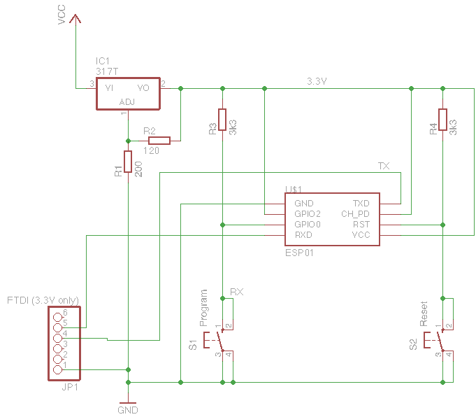
It’s super simple. I feed in 5V to VCC, and the LM317T outputs 3.3V. The resistors values were calculated using the look up table here.
The two 3k3 resistors ensure that GPIO0 and RST (Reset) pins are held HIGH during boot up (which is required for normal operation).
To program the device, (and you’ll quickly get used to this little dance) you push the RESET, then the PROGRAM button, then release the RESET button first, followed by the PROGRAM button. This ensures that the GPIO0 pin is held LOW during the device boot sequence, putting us in programmer mode!
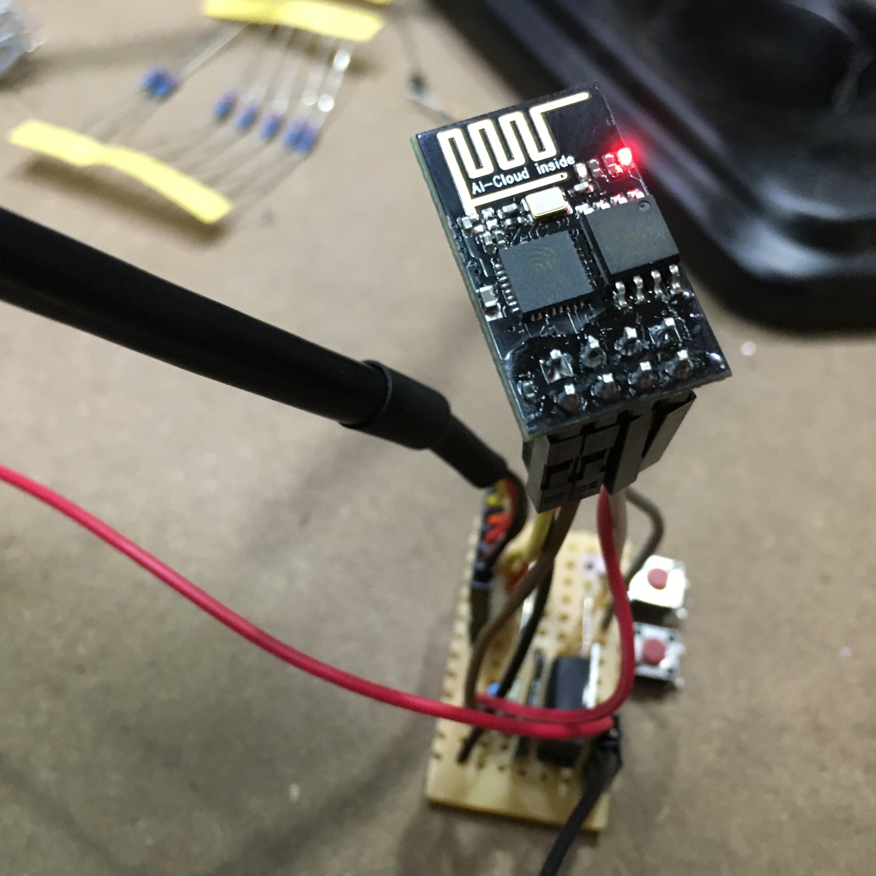
If all goes well you should see a constant red LED, and a flickering blue LED when you are talking to the device over FTDI.
Here is an artistic picture of my cobbled-together breadboard (it’s the blurry bit down the bottom):