Reverse engineering a Fujitsu Air Conditioner Unit – Baseline communication
I took the remote unit off the wall again, and this time removed the signal wire fro the remote and attached it to my Oscilloscope.
And this is signal that comes from the outdoor unit.
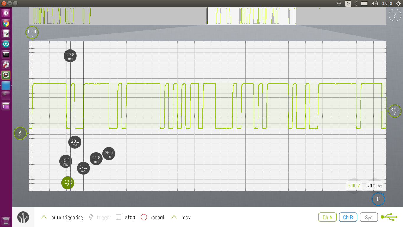
I’m not sure if I stuffed up my reading the last time, but it looks like the pulse width is 2ms.
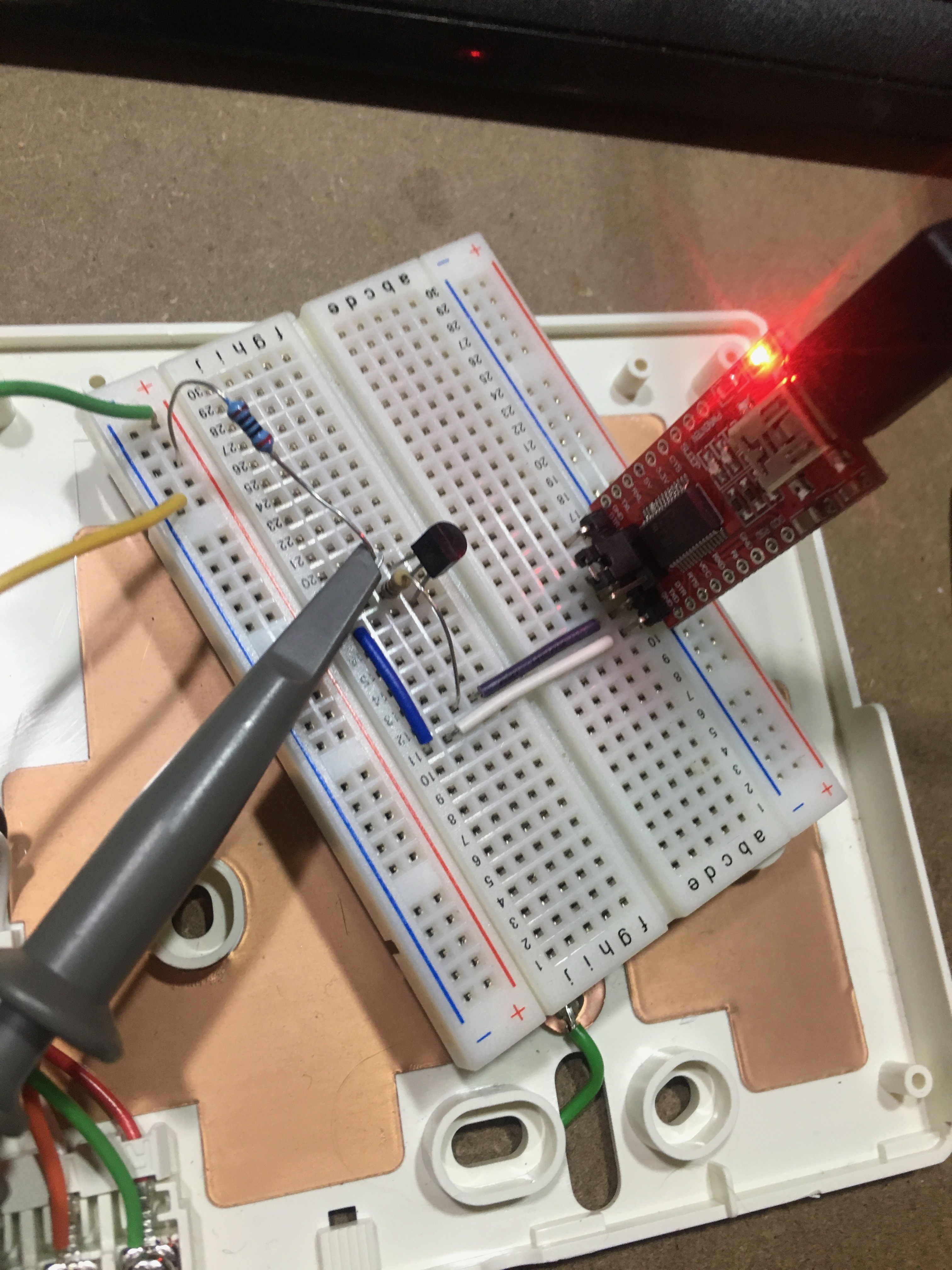
Really, I needed to replay this and see if I could get my test unit to initialise. I thought about using an Ardiuno, so I googled bit banging serial to see the best way to do it. One of the results that caught my eye was another Hackaday article entitled “Introduction to FTDI bitbang mode“. I had literally just cleaned up my workbench and found a FTDI module. Perfect!
I knocked up a little circuit that drove a transistor from 0V to 12V, and adapted the code from the article to control the FTDI modules CTS line. I had to reduce the sleep time to 1.8ms to adjust for kernel context switches (I’m guessing) while talking to the adapter. I got it pretty close to 2ms though.
I wired it up to the controller, and got one step closer – now instead of timing out and flashing C0 12, it just sits flashing “9C” forever.
My guess? This communication protocol works on one-wire – I’m not releasing the line, so the remote never gets a chance to send a response. It looks like I’ll need some sort of tri-state buffer, so I can set the line to high-impedance after I’ve sent the preamble.
I was curious to see if I could get any other clues to the protocol, so I started poking around the big chip on the PCB. One of the pins receives the same signal the signal line does, except it’s inveted and 0-5V! I went and looked up the chip (it’s a UPD78F0393 from NEC – I’m so glad the remote manufacture labelled all their chips nicely), and that pin (#75) is labelled RXD0. That sounds like a serial receive line to me!
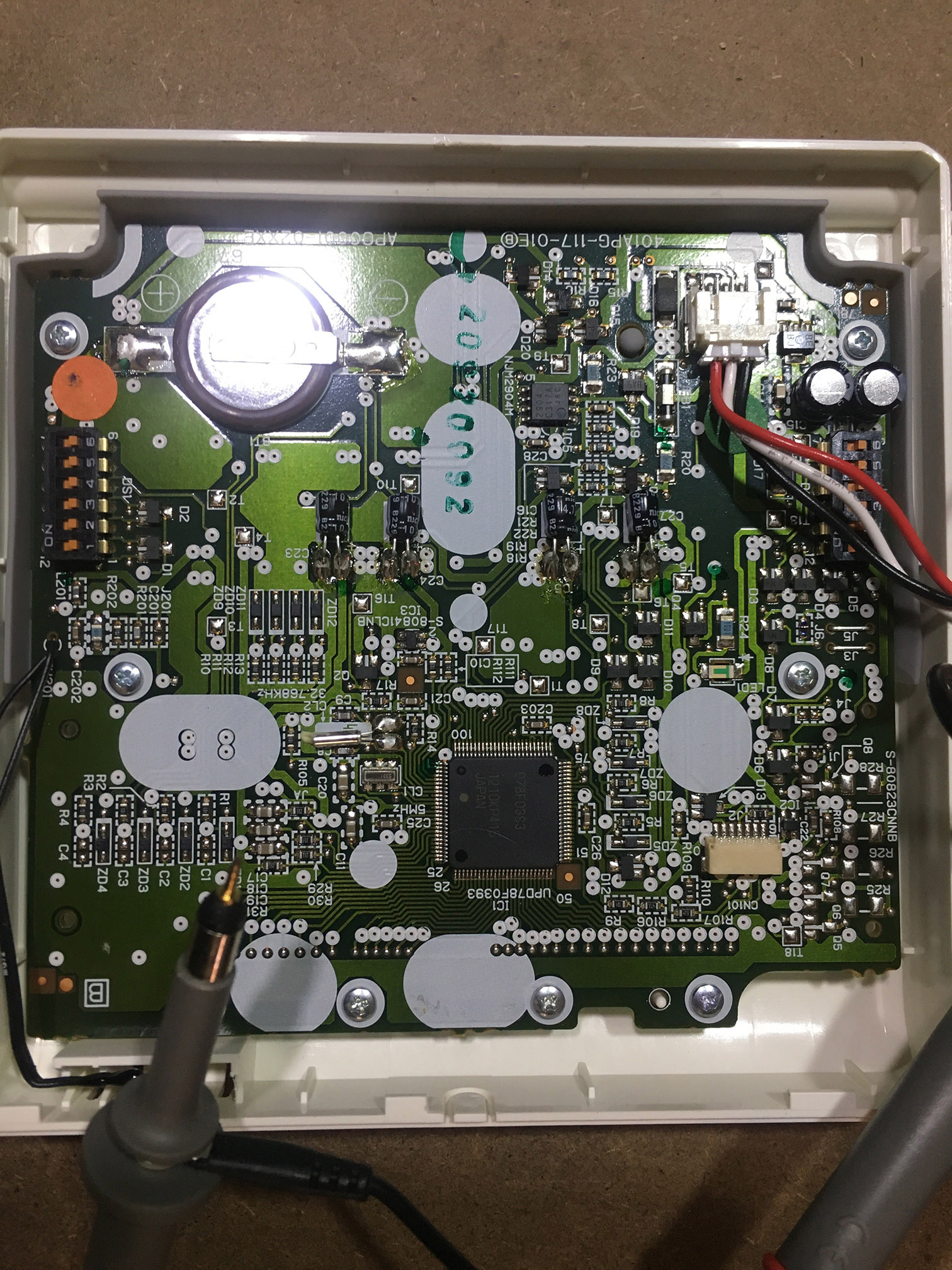
Pin 76 is labelled TXD0, which I’m guessing is the transmit line. This should make decoding stuff way easier, because I’ll be able to see what is actually being transmitted and received separately. Win!
I’m going to try and trace out the front-end to this – so far I see a NJM2904 (an op-amp) is on the path – my guess is that is the thing inverting the signal and driving it to 12V. Tracing this circuit out should allow me to build a compatible circuit from my microcontroller.