Converting a Makibox into a PCB Mill – Building the X-axis
Re-designing the X-axis of my Makibox to PCB mill conversion has been a challenge in constraints. Due to an ordering mishap, and lack of engineering designs for the spindle I have been racking my brain to re-use the parts I have to create a workable X-axis.
The three constraints I have to work with:
- The spindle can’t be too low – I want at least 70mm of vertical travel
- The spindle can’t be too high – The further the cutting tool is from the centre of the holder, the more torque it needs to deal with
- The spindle can’t be too far forward – I’d like the cutting tool to sit as close to the centre of the frame, so it can reach the full range of motion. The shaft of the spindle sits around 40mm from it’s mounting plate, which puts it out nearly 80mm when you include the Z-axis linear driver.
I looked at mounting the stepper motor on top of the vertical extrusion, but it failed constraint 3. It also gave me no where to mount the top steel rod. I toyed around with moving the steel rods but centred either side of the lead screw seems the best place for them.
I settled on a design where the motor hangs off the side of the vertical extrusion, with the steel rods mounted either side.
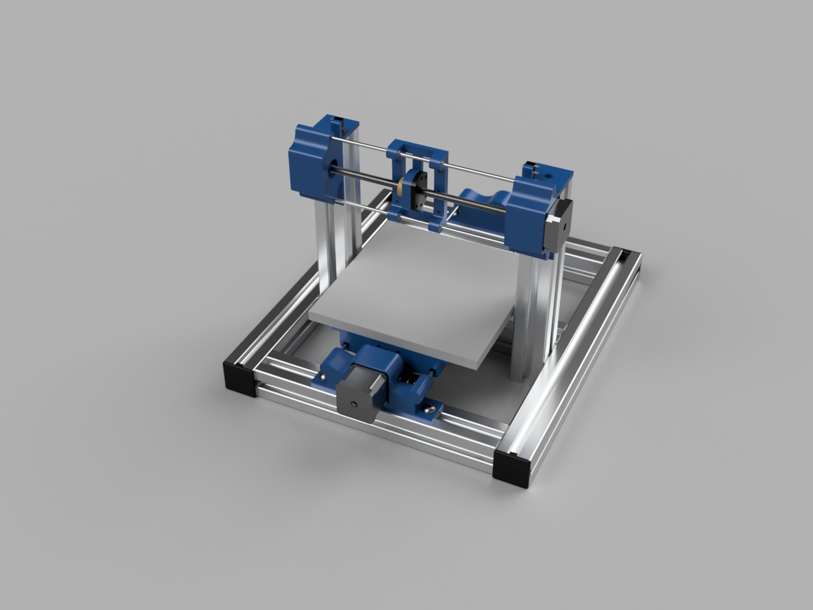
The test build
After printing motor and bearing holders, and the carriage I put everything together. I held the spindle against the carriage to get an idea of placement, and it became clear that the 4mm steel rods were going to flex too much under load.
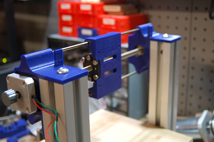
They would be fine for a 3D printer or as a laser cutter, but even the small forces from a PCB mill bit would cause issues. It was time to replace the rods with something more robust.
I jumped on Aliexpress and found these 200mm linear guides that have a 12mm steel rod, and support for the full length, so bending should not be an issue.
I also decided to replace the Y-axis rods with the 400mm version of the linear guide. This will remove the flex in the bed and will make alignment easier (the three points of contact design I used was difficult to square).
While I was at it I ordered some linear bearings for the Z-axis for good measure.
A substantial redesign.
I have one 205mm cross bar, which a perfect support for one of the linear rails – I’ll need another one. I’ll also need another two, taller vertical extrusions to hold the cross bars. The two shorter vertical extrusions will hold the motor.
Here is a rough render without any joining hardware so you get the idea.
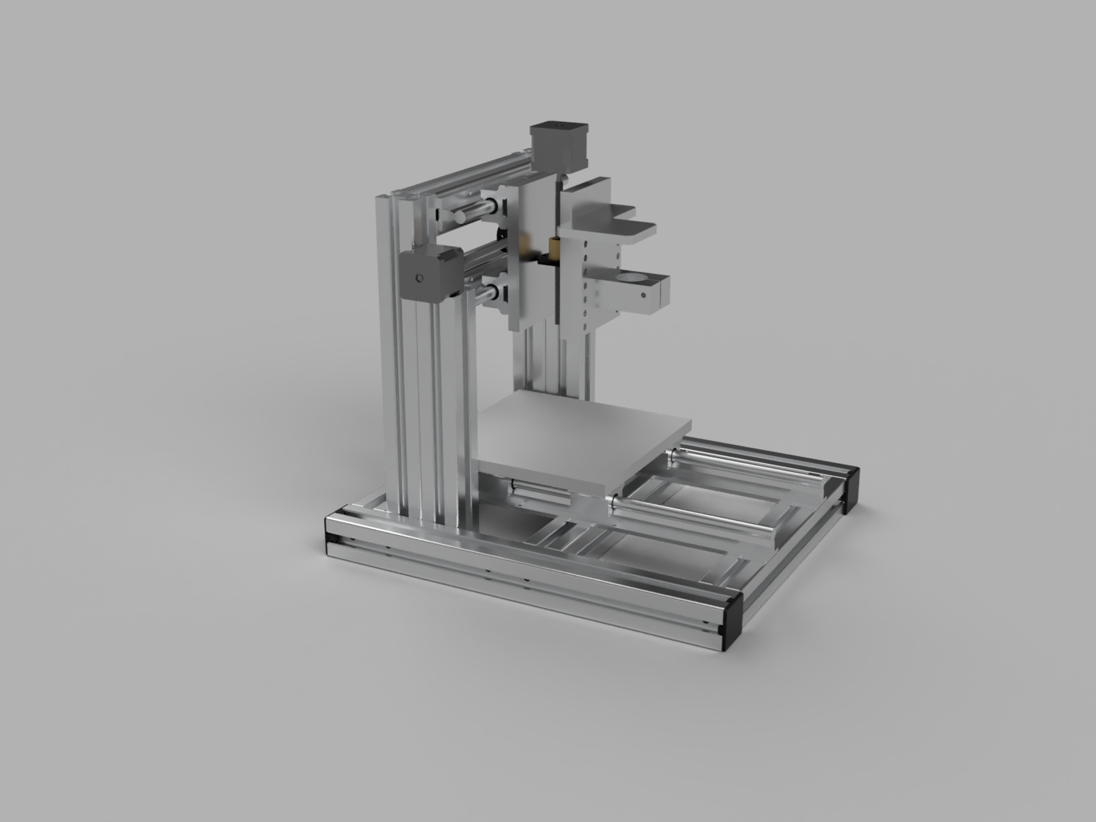
I’ve had to move the vertical extrusions to the rear of the frame (which is fine, there are still two connection points there), giving the spindle plenty of room.
I’m going to design and print some new motor and bearing mounts for the X and Y axis. They will be much simpler as they no longer need to support the steel rods.
The rear support for the Z-axis will be 10mm aluminium, as I can get the supplier to cut it to the required 138mm length. The end caps – which act as a motor holder and rod support – will be plastic to start (I don’t have facilities to mill aluminium… yet). My intention is to mill replacements once the machine is complete.