Garage Door Opener – Hardware test
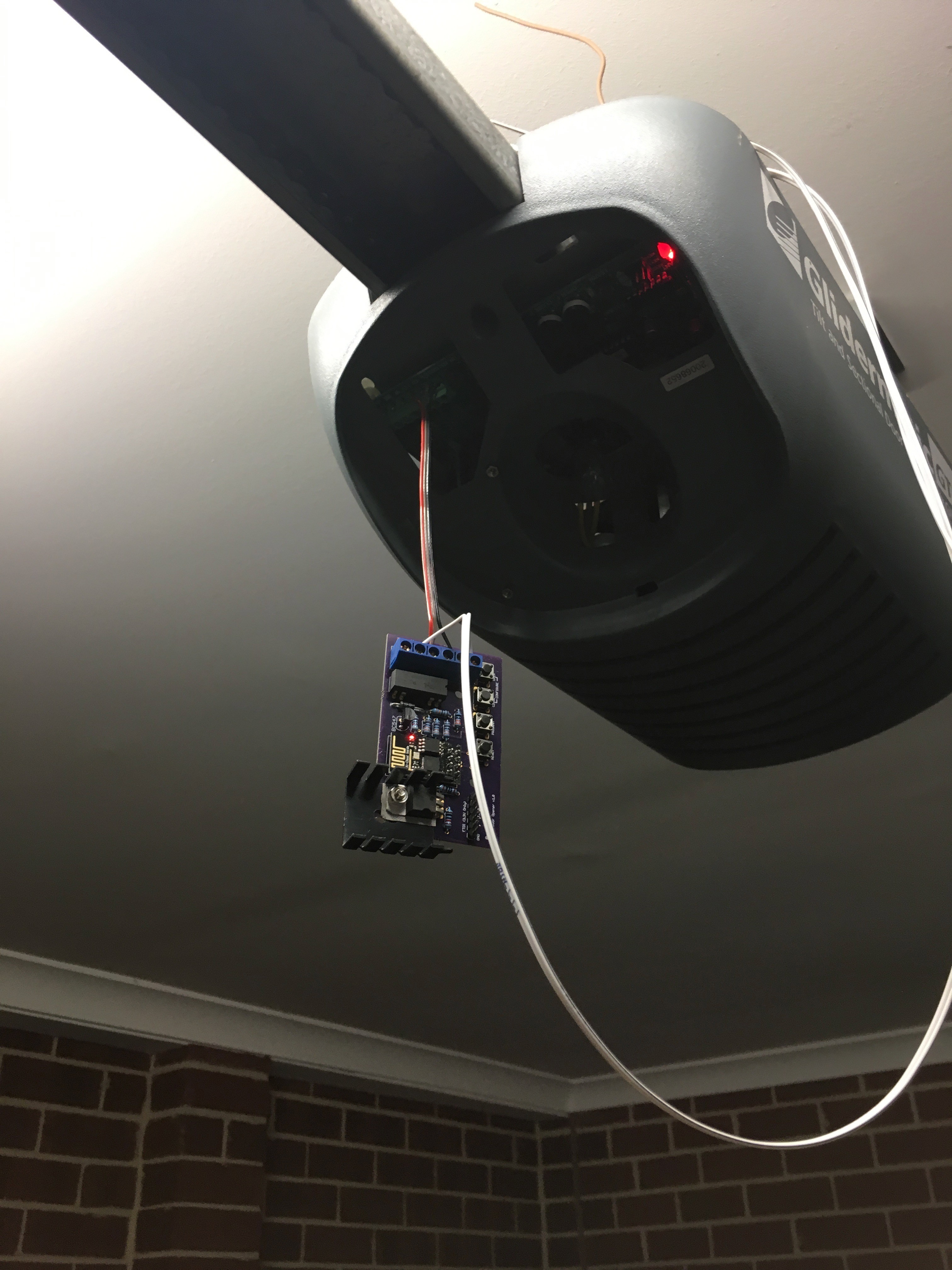
Even though I still have to complete the captivate portal, and over-the-air updates, It seemed like a good time to wire the controller in and see how it all works off the bench.
It’s a good thing I did, as I discovered a few issues with the board.
Excuse the wiring, it’s just temporary…
Originally, I had two switches: one of when the door was completely open, and one for completely closed. Based on the last state, I could guess whether the door was opening or closing. I must admit, I realised long after I ordered and built the board that I really only needed one switch that indicated the closed position. Good thing really, because the device got completely confused after I installed it.
Back story
Because of the limited number of IO pins on the ESP8266-01, I had to pull some tricks to give me two switches and a relay (I can’t take credit, this is an amalgam of a bunch of stuff I found Googling).

There are 4 GPIOs, two of which are shared with the TX and RX pins on the serial port. To make things even more interesting, GPIO0 needs to be held high on boot, otherwise the device goes in to programming mode.
This means GPIO0 is no good as a switch interface – if there was a power outage and the switch attached to GPIO0 was closed as it rebooted, the device would be stuck in program mode.
Conversely, when the device boots up, there is a bit of chatter on TX, so putting the relay on that would be risky – a reboot could cause the door to trigger, and open it when no one was home.
Wiring the relay to GPIO0 and GPIO2 is quite easy, pull them high with pull-up resistors, then switch them to outputs during the setup phase. Setting them both low at the same time sets the relay up. Pulling GPIO2 up, drives the base of a transistor and energises the relay. While the output of the chip could drive the relay directly, I’m actually using a 12v relay that is driven from the convenient 12V output from the garage door controller, so the transistor is required to switch the higher voltage from the lower 3.3V coming out of the regulator.
The “closed” switch is wired to the RX pin, and the “open” switch is wired to the TX pin. This means that the Serial Port is disabled, which can make debugging difficult, so as I work, I usually disable the switches.
This all worked fine on my bench, but as soon as I installed it the close switch wouldn’t register properly, and I couldn’t work out for the life of me why. I suspect the internal state machine wasn’t transitioning properly, possibly because of contact bounce, but it turns out it didn’t matter – I also found what I would call a show stopper: I discovered that if the TX pin was held high (ie the device booted when the door was open) it would never start.
Not ideal.
In a quick refactor of the code, I disabled the state machine, replacing it with a simpler open/close state – if the “closed” switch is closed, the device reports closed, if it’s open, it reports open. Keep it Simple. Who knew, right? Another nice side effect is I can use Serial.println for debugging again. Bonus.
So that brings the mistake count for that board up to four – thankfully all workaroundable (totally a word)fairly easily:
- “Open” switch not needed
- TX and RX pins on the FTDI connector are transposed (fixed by modifying my FTDI cable, which I’m sure will come back to bite me at some point)
- Originally, the GND for both switches shared a screw terminal, although now I can get rid of the open switch, I can keep the board to five screw terminals.
- No room for the heatsink
- (Improvement) Add a jumper to switch between using the 5V off the FTDI cable and an external supply – I was using a fly leads soldered to the bottom of the board while testing.
As a PCB board designer, I’m an excellent software engineer.