@madpilot makes

Garage Door Opener – Connecting the ESP8266 with TLS

While I want to do full CA verification, I’m waiting on some of the bugs to get ironed out of the ESP8266 Arduino library, so I’ll take a shortcut for the moment, and use fingerprinting to verify the server certificate (It should be pretty easy to move to CA verification down the track).

To do this, we need three pieces of information:

  1. Client certificate
  2. Client secret key
  3. Server fingerprint

We have already generated the certificate and the secret key, so let”s generate a fingerprint for the server certificate. We can use OpenSSL to do this:

openssl x509 -in mosquitto/etc/certs/mqtt.local.crt.pem -sha1 -noout -fingerprint

This will generate a 160bit sha1 string, that may look a little like this:

SHA1 Fingerprint=DA:39:A3:EE:5E:6B:4B:0D:32:55:BF:EF:95:60:18:90:AF:D8:07:09

Convert PEM to DER

I was reading through the docs, and while the axTLS says it supports PEM, I found that I needed to convert the PEM format certificate (which is ASCII based) to DER which is binary.

Again, OpenSSL to the rescue:

openssl x509 -outform der -in garage.local.csr.pem -out garage.local.csr.der
openssl x509 -outform der -in garage.local.key.pem -out garage.local.key.der

Loading the certificates

Down the track, I’ll be able to upload the certificate and key via the administration console (certificates expire, and need to be updated), which means storing them in the code makes little sense. Instead I’m going to store them on the flash as a file.

Thankfully there is a tool that makes uploading files to the SPIFFS filesystem super simple. Gratuitously stolen from the Filesystem Read Me:

ESP8266FS is a tool which integrates into the Arduino IDE. It adds a menu item to Tools menu for uploading the contents of sketch data directory into ESP8266 flash file system.

  • Download the tool: https://github.com/esp8266/arduino-esp8266fs-plugin/releases/download/0.2.0/ESP8266FS-0.2.0.zip.
  • In your Arduino sketchbook directory, create tools directory if it doesn’t exist yet
  • Unpack the tool into tools directory (the path will look like_<home_dir>/Arduino/tools/ESP8266FS/tool/esp8266fs.jar_)
  • Restart Arduino IDE
  • Open a sketch (or create a new one and save it)
  • Go to sketch directory (choose Sketch > Show Sketch Folder)
  • Create a directory named data and any files you want in the file system there
  • Make sure you have selected a board, port, and closed Serial Monitor
  • Select Tools > ESP8266 Sketch Data Upload. This should start uploading the files into ESP8266 flash file system. When done, IDE status bar will display SPIFFS Image Uploaded message.

Copy the two der files in to the data directory, and run the data upload function (I renamed them client.key.der and client.crt.der because that kind of makes more sense in this context). To load the files, the code looks a little like this:

// We need to use WiFiCLientSecure to the encryption works
WiFiClientSecure wifiClient

SPIFFS.begin();
File ca = SPIFFS.open("/client.crt.der", "r");
if(!ca) {
  Serial.println("Couldn't load cert");
  return;  
}

if(wifiClient.loadCertificate(ca)) {
  Serial.println("Loaded Cert");
} else {
  Serial.println("Didn't load cert");
  return;
}
  
File key = SPIFFS.open("/client.key.der", "r");
if(!key) {
  Serial.println("Couldn't load key");
  return;  
}

if(wifiClient.loadPrivateKey(key)) {
  Serial.println("Loaded Key");
} else {
  Serial.println("Didn't load Key");
}

The device will connect at this point, and the mosquitto server will be happy. It will use the name on the certificate as the client name, and the connection will be encrypted.

However, I not verifing the server yet. I will do that using the verify function

PubSubClient client("mqtt.local", 8883, callback, wifiClient); //set  MQTT port number to 8883 as per //standard

wifiClient.connect("mqtt.local", 8883);
  
if(wifiClient.verify("DA 39 A3 EE 5E 6B 4B 0D 32 55 BF EF 95 60 18 90 AF D8 07 09", "mqtt.local")) {
  Serial.println("connection checks out");
  wifiClient.stop();

  if(client.connect("garage")) {
    Serial.println("Connected");
    client.subscribe("test");
    client.publish("test", "hello world");    
  } else {
    Serial.println("Not connected");
  }
} else {
  wifiClient.stop();
  Serial.println("connection doesn't check out");
}

Notice that all of the colons have been replace with spaces.

Because of the way the PubSubClient works, I need to make a (pre?)connection to the server to do the verification. It’s pretty simple – connect, verify and disconnect, then continue with the PubSub connection.

There is a problem here – the mDNS name won’t actually resolve at this point. Because the DNS resolver doesn’t support it.

Ok, that isn’t strictly true – every DNS resolver CAN resolve mDNS, but you need to hit a special DNS server and port (224.0.0.251 on port 5353), which I haven’t worked out how to do with the Arduino library yet…

Garage Door Opener – So, the ESP8266 does support TLSv1.2

I was digging around the ESP8266 github page, as there was an announcement that it now supports CA verification (it ALMOST does – there was a regression bug that means it’s still not working), but I noticed that the last release (2.3.0 at time of writing) is actually quite old – it was released in June.

I was going through recent commit messages, and noticed there had been quite a bit of work around integrating axTLS, which is a tiny TLS library specifically designed for computers with small memory footprints (AKA microcontrollers).

This piqued my interest.

It has been said that the ESP8266 doesn’t support TLSv1.2, because of a buggy implementation in the firmware, which I had verified earlier in testing and hence configuring MQTT to force TLSv1.1.

By including axTLS as part of the Arduino library, and not relying on the ESP8266 API, I wondered if TLS1.2 was now supported.

Turns out it is!

It does mean we’ll have to use a “unstable” version of ESP8266 library. This means other stuff might not work, we need to install it using git, and it’s up to us to keep everything up to day.

Thankfully, it isn’t that difficult to install the library using git.

First, remove the existing ESP8266 library using the board manager – find it using the search function, then hit remove.

Now, you can manually install – Instructions are here. Don’t forget to re-select the right board and to set the CPU frequency to 160Mhz!

Now, that regression bug. It stops client certificates being sent for verification, which is bad for us, so we’ll need to roll back a couple of commits. To do that:

cd ~/Arduino/hardware/esp8266com/esp8266
git checkout -b pre-axtls-2 d6e38f0abd2e1bf796a32e8b1a24d37fdc7daaf8

This creates a new branch based on an older revision that seems to still work ok.

Modify mosquitto to use TLSv1.2

This one’s pretty easy: Remove the tls_version line

#tls_version tlsv1.1

Then remove

"--tls-version", "tlsv1.1", 
from both mosquitto-client/Dockerfile.pub and mosquitto-client/Dockerfile.sub.

Run

docker-compose build
and start the server with
docker-compose up

You should see “Hello world” in there somewhere. Next up, the Arduino side of things…

Garage Door Opener – Adding TLS

While having a username and password is better than an open MQTT server, the credentials are still being sent in plain text, so anyone with a packet sniffer could intercept them and then gain access to our server.

To avoid this, let’s setup TLS (commonly, but maybe not correctly known as SSL) to encrypt the connection and kept the credentials secret.

TLS 101

TLS provides a chain of trust, allowing two computers that know nothing about each other to trust each other.

Let’s look at how this works in the context of a browser hitting a secure website, as this is an example we should all be familiar with.

At a really high level, both your computer and the server have a Certificate Authority (CA) that they both implicitly trust (there is actually more than one, but let’s keep it simple). When you hit a website that is secured the server sends it’s certificate to the browser, which does some complicated maths and verifies the certificate against the CA – if the numbers work out, your browser can be confident that the certificate is legitimate and that the secure site is who it says it is.

Web servers generally don’t care who the client is, so they rarely ask for a client certificate, but in other applications (like this garage door opener) the server will also verify the client against it’s CAs.

After both computers are happy they are talking to the right people, they will exchange a set of symmetric keys that both computers will use to communicate. Symmetric keys are much faster to encrypt and decrypt that asymmetric keys, but it requires both sides to have the same key.

To do that securely, a symmetric key is generated, encrypted using the other computer’s public key, sent securely across the wire and then decrypted – now both computers have the key and they can start talking.

Setting up our own trust network

Enough theory! The first thing to do is generate a CA. If you have OpenSSL installed on your computer (Linux and OSX users more than likely will), you can generate a CA on the command line:

openssl req -new -x509 -days 3650 -extensions v3_ca -keyout ca.key.pem -out ca.crt.pem

You’ll be asked for a PEM password – make this something difficult to guess and then store it in your password manager.

This is literally the key to the city. If someone gets hold of your ca.crt.pem and ca.key.pem, and can guess your password, then they can generate their own valid certificates – not good. Fill in the details as you are asked – these details aren’t super important as this is a personal CA, but make the values something you will recognise. The common name can be whatever you want. Now that you have your CA certificate (ca.crt.pem) and your CA.key (ca.key.pem) you can generate some certificates.

An aside: If you have a password manager that supports notes, I’d recommend saving these files in the there and deleting them from your file system after you have generated any certificates that you need.
Generate a server certificate

For this to work, it’s best to use actual domain names for servers and clients – the easiest way to do this is setting up mDNS, via avahi (linux) or bonjour (OSX) – Windows probably has something too – let’s assume that the name of the computer running MQTT is mqtt.local and the name of the garage door opener will be garage.local.

# Generate a key
openssl genrsa -out mqtt.local.key.pem 2048
# Create a Certificate signing request
openssl req -out mqtt.local.csr.pem -key mqtt.local.key.pem -new

Again, fill in the details as you are asked.

The MOST important one is Common Name. IT MUST MATCH THE DOMAIN. So in our case: mqtt.local

# Sign the certificate
openssl x509 -req -in mqtt.local.csr.pem -CA ca.crt.pem -CAkey ca.key.pem -CAcreateserial -out mqtt.local.crt.pem -days 365

You will be asked for the password you entered when you created your CA.

Note that the certificate is valid for 365 days – you’ll have to generate a new one in a years time. You can decide if you want to make it longer or shorter.

Generate the client certificate

Generating a client certificate looks a lot like the generation of a server certificate – just with different filenames.

# Generate a key
openssl genrsa -out garage.local.key.pem 2048
# Create a Certificate signing request
openssl req -out garage.local.csr.pem -key garage.local.key.pem -new

The common name this time should be garage.local

# Sign the certificate
openssl x509 -req -in garage.local.csr.pem -CA ca.crt.pem -CAkey ca.key.pem -CAcreateserial -out garage.local.crt.pem -days 365

Setting up Mosquitto

Now we have all of the certificates that we need, let’s setup mosquitto to use it.

Create a ca_certificates and certs directory in the mosquitto/etc docker folder

mkdir mosquitto/etc/ca_certificates
mkdir mosquitto/etc/certs

and copy ca.crt.pem to the ca_certificates folder and mqtt.local.crt.pem and mqtt.local.key.pem to the certs folder. Finally update the etc/mosquitto.conf file to look something like this:

persistence true
persistence_location /var/lib/mosquitto/
password_file /etc/mosquitto/passwd
allow_anonymous false
cafile /etc/mosquitto/ca_certificates/ca.crt.pem
certfile /etc/mosquitto/certs/mqtt.local.crt.pem
keyfile /etc/mosquitto/certs/mqtt.local.key.pem
port 8883
tls_version tlsv1.1
include_dir /etc/mosquitto/conf.d

Notice we have changed the port to 8883, which is the standard port for secure MQTT. We are also still authenticating via username and password.

We are explicitly forcing TLS version 1.1 because the ESP8266 implementation of 1.2 is buggy, and will fail.

Save the file, and run

docker-compose build mosquitto

Because we aren’t verifying the certificates, we can use the garage.local certificate on the command line to test everything out.

Create the ca_certificates and certs directories, this time in mosquitto-client

mkdir mosquitto-client/ca_certificates
mkdir mosquitto-client/certs

Copy ca.crt.pem to the ca_certifications directory and both the garage.local.crt.pem and garage.local.key.pem files to the certs directory.

Now, modify the Dockerfile.sub ENTRYPOINT to look like this:

ENTRYPOINT [ "mosquitto_sub", "-h", "mosquitto", "-p", "8883", "--tls-version", "tlsv1.1", "--cafile", "/ca_certificates/ca.crt.pem", "--insecure", "--cert", "/certs/garage.local.crt.pem", "--key", "/certs/garage.local.key.pem" ]

and the Dockerfile.pub ENTRYPOINT to look like:

ENTRYPOINT [ "mosquitto_pub", "-h", "mosquitto", "-p", "8883", "--tls-version", "tlsv1.1", "--cafile", "/ca_certificates/ca.crt.pem", "--insecure", "--cert", "/certs/garage.local.crt.pem", "--key", "/certs/garage.local.key.pem" ]

Finally, run

docker-compose build

and

docker-compose up

And everything should connect again, but this time securely!
All of these instructions gratuitously stolen from: https://mosquitto.org/man/mosquitto-tls-7.html

Garage Door Opener – Let’s connect

So, now we have an MQTT server, lets see if we can get the ESP8266 to connect to it.

I’m going to use Nick O’Leary’s pubsubclient library. It’s pretty easy to install – find Manage Libraries in the Sketch Menu, search for pubsubclient and it should appear. Hit install.

After we physically connected to the WIFI (Which we’ll do via via hard coding the SSID and passkey for the moment – we’ll do that properly later), there are two things we need to do:

  1. Connect to the MQTT server – no security for the moment, we’ll work up to that
  2. Subscribe to a message. We provide the library with a callback function that gets called every time the server receives a message topic that we are subscribed to.

Here is the some proof of concept code that does all of that:


#include <ESP8266WiFi.h>
#include <ESP8266mDNS.h>
#include <PubSubClient.h>

#define SSID "your-wifi-ssid"
#define PASSKEY "your-wifi-password"
#define MQTT_IP "ip-address-of-the-mqtt-server"
#define MQTT_PORT 1883
#define MQTT_NAME "garage"

#define TOPIC "test"

#define QOS_LEVEL 0

// PubSub client
WiFiClient espClient;
PubSubClient pubSubClient(espClient);
void PubSubCallback(char* topic, byte* payload, unsigned int length);
long lastPubSubConnectionAttempt = 0;

void PubSubSetup() {
  pubSubClient.setServer(MQTT_IP, MQTT_PORT);
  pubSubClient.setCallback(PubSubCallback);
}

boolean PubSubConnect() {
  Serial.print("Connecting to MQTT server...");

  if(!pubSubClient.connect(MQTT_NAME)) {
    Serial.println("\nCouldn't connect to MQTT server. Will try again in 5 seconds.");
    return false;
  }

  if(!pubSubClient.subscribe(TOPIC, QOS_LEVEL)) {
    Serial.print("\nUnable to subscribe to ");
    Serial.println(TOPIC);
    pubSubClient.disconnect();
    return false;
  }

  Serial.println(" Connected.");
  return true;
}

void PubSubLoop() {
  if(!pubSubClient.connected()) {
    long now = millis();

    if(now - lastPubSubConnectionAttempt > 5000) {
      lastPubSubConnectionAttempt = now;
      if(PubSubConnect()) {
        lastPubSubConnectionAttempt = 0;
      }
    }
  } else {
    pubSubClient.loop();
  }
}

void PubSubCallback(char* topic, byte* payload, unsigned int length) {
  char *p = (char *)malloc((length + 1) * sizeof(char *));
  strncpy(p, (char *)payload, length);
  p[length] = '&#92;&#48;';

  Serial.print("Message received: ");
  Serial.print(topic);
  Serial.print(" - ");
  Serial.println(p);

  free(p);
}

void connectWifi(const char* ssid, const char* password) {
  int WiFiCounter = 0;
  // We start by connecting to a WiFi network
  Serial.print("Connecting to ");
  Serial.println(ssid);

  WiFi.disconnect();
  WiFi.mode(WIFI_STA);
  WiFi.begin(ssid, password);
  while (WiFi.status() != WL_CONNECTED &amp;&amp; WiFiCounter &amp;amp;lt; 30) {
    delay(1000);
    WiFiCounter++;
    Serial.print(".");
  }

  Serial.println("");
  Serial.println("WiFi connected");
  Serial.print("IP address: ");
  Serial.println(WiFi.localIP());
}

void setup() {
  Serial.begin(115200);
  connectWifi(SSID, PASSKEY);
  PubSubSetup();
}

void loop() {
  PubSubLoop();
}

To run this, first fire up our MQTT server using docker-compose up, next load up the above code on the ESP8266, replacing the constants at the top of the file with the relevant settings.

If you are running Docker on Linux, or using Docker for Mac; or Docker for Windows the IP address of the server will be the same as the IP address of your computer.

If you are running docker-machine, you will need to run docker-machine ip to find out the local IP address.

Open up the serial monitor and you should see something like this:

Connecting to [what ever your ssid is].
WiFi connected
IP address: [some IP address]
Connecting to MQTT server... Connected.

Now, if we publish a message on to the queue

docker-compose run mosquitto-publisher -t "test" -m "Hello Arduino!"

We should see the Arduino consuming the message:

Message received: test - Hello Arduino!

If you don’t see the message, there should be hints in the serial monitor about what went wrong.

Things to look out for:

  • If you can’t connect to the WiFI, check your SSID and passkey
  • If you can’t connect to the MQTT server, check your IP address. Also, check the docker output – you should see a message when the Arduino connects.

Garage Door Opener – How can I make this garage door opener secure?

One of the design goals for this project was a secure system – this device can open my garage, and I don’t really want just any person to be able to do that!

Disclaimer: I’m not a security expert! If you find holes in my logic, please let me know!

The most obvious way to interface with the controller was to setup some sort of server that a controller (eg an iPhone app) talks to. The problem with this is that an open network port is an attack vector – if a good guy can connect to a network port, so can a bad guy. While I could set up a username or password, having a port open potentially means buffer overflows, and since I’m not really a C/C++ guy this a big problem for me – I mean a lot of really smart people avoid writing servers in C…

After some research, I found this paper (PDF) talking about the use of the publish/subscriber pattern (AKA pub/sub), where a device connects to as server and subscribes to event notifications. This means there is no port open on the device, so even if an attacker found it’s IP address, there is no way for them to connect to it. It seems MQTT is the IOT pub/sub system of choice (it drives a lot of public IOT platforms).

This of course is not without other issues (not exhaustive – please suggest more if you can think of others):

  1. Problem: If an attacker got on the network, they could just connect to the MQTT server and send a “open” command. Solution: Access control lists (ACL): Only allow certain MQTT clients send certain commands. We would need some way for the server to verify who the client is…
  2. Problem: What if an attacker managed to spoof the IP or MAC address (perhaps through ARP poisoning) they could become a legitimate MQTT server, allowing them to send an open command. Solution: Verify the identity of the server. TLS certificates can help with that. Using a certificate signed by a custom Certificate Authority (CA) means we can guarantee the server is who it says it is. This also fixes the client verification problem from point 1.

After a quick search, I found the mosquitto project – an open source MQTT server which looked pretty easy to setup, supports ACLs and TLS.

Docker all the things

I decided to set it up a test environment using docker, as it makes dependency management much easier, and also makes the setup scriptable, so when it comes time to deploy to “production” I know exactly what I need to do.

You can clone my git repository to get started (I’ve tagged each of the steps so you can play at home – we’ll start with mqtt-1):

git clone https://github.com/madpilot/home-automation
cd home-automation
git checkout -b mqtt-1 mqtt-1
docker-compose build
docker-compose up

Congratulations! You now have a working MQTT server running on port 1883. Because it hasn’t configured it yet, the server has no authentication or authorisation – that’s fine for the moment – let’s get the baseline working, then we can add the security layers later.The easiest way to test the server is to use the mosquitto command line client. I’ve included these as part of the docker-compose cluster – in fact, when you ran docker-compose, a subscriber was automatically created (subscribed to the “test” channel) and publisher publishes the first message.

Look through the output on the screen. If you see:

mosquitto-subscriber_1  | Hello World

Everything has worked!You can try it out yourself – run the following command:

docker-compose run mosquitto-publisher -t "test" -m "Hello again"

And you should see

mosquitto-subscriber_1  | Hello again

I’ve been a bit tricky by using a docker entry point to hide away the full command to make sending messages much easier. The full command that gets called is

mosquitto_pub -h mosquitto -t test -m "Hello again"

Which tells mosquittopub to connect to the server with a host name of _mosquitto (Which is set by docker), publish to the “test” channel, and send the message “Hello again”.Now that we have a working MQTT server and a way of testing things, we can start looking at the Arduino side of things.

Garage Door Opener – Setting up the Arduino IDE for the ESP8266

Thankfully, setting up the Arduino IDE to program the ESP8266 this bit was way easier than I thought – the team behind the Arduino library have done a pretty awesome job. I’m not going to duplicate the steps here – the Github page does a great job of explaining it.

Now you should be able to pick the “Generic ESP8266 Module” from the board list. I had to make a guess at the settings, as I had no idea what type I had – the defaults were fine in my case.

Don’t forget to select the right port after you have plugged in the FTDI cable (Tools > Port) – on my Ubuntu machine it switches between /dev/ttyUSB0 and /dev/ttyUSB1 every time I plugged it in, so if you can’t upload code – check that the port hasn’t changed.

Garage Door Opener – Programming the ESP8266

I has an ESP8266-01 kicking around my workshop just waiting for a project, so the garage door opener was a perfect choice – it only needed one output, and two inputs.

The first problem I had though, was I needed to program it. I read that you can use a 3.3V FTDI cable, which I already had – sort of. It’s will interface at 3.3V, but the VCC is 5V.

My first attempt was just using a simple resistor divider, which didn’t work – I’m guessing the load caused to much of a voltage drop.

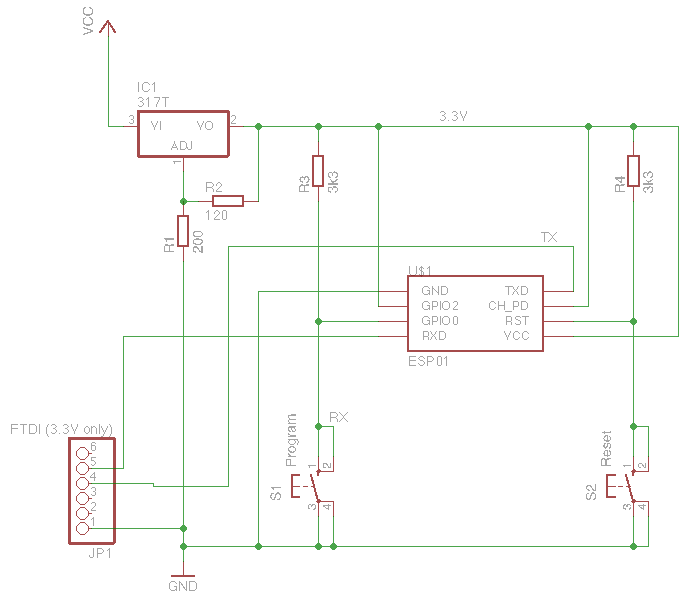
So I grabbed a LM317T, a couple of switches, and some resistors to build a small interface board. This is based on a number of different circuits I found searching the internet.

ESP8266 Programmer scematic

It’s super simple. I feed in 5V to VCC, and the LM317T outputs 3.3V. The resistors values were calculated using the look up table here.

The two 3k3 resistors ensure that GPIO0 and RST (Reset) pins are held HIGH during boot up (which is required for normal operation).

To program the device, (and you’ll quickly get used to this little dance) you push the RESET, then the PROGRAM button, then release the RESET button first, followed by the PROGRAM button. This ensures that the GPIO0 pin is held LOW during the device boot sequence, putting us in programmer mode!

If all goes well you should see a constant red LED, and a flickering blue LED when you are talking to the device over FTDI.

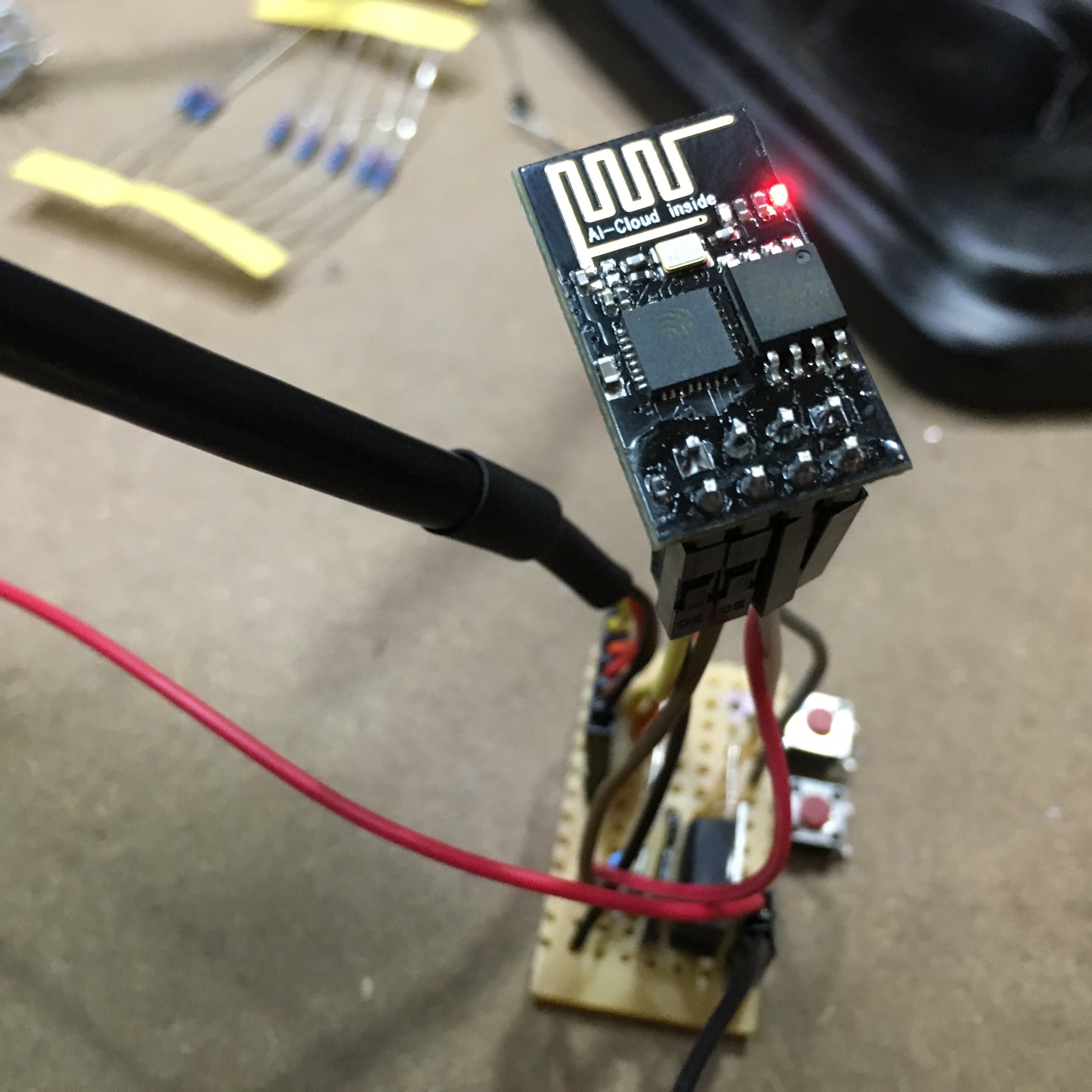
Here is an artistic picture of my cobbled-together breadboard (it’s the blurry bit down the bottom):

My Ghetto ESP8266 programmer

Previous