Garage Door Opener – Hardware test
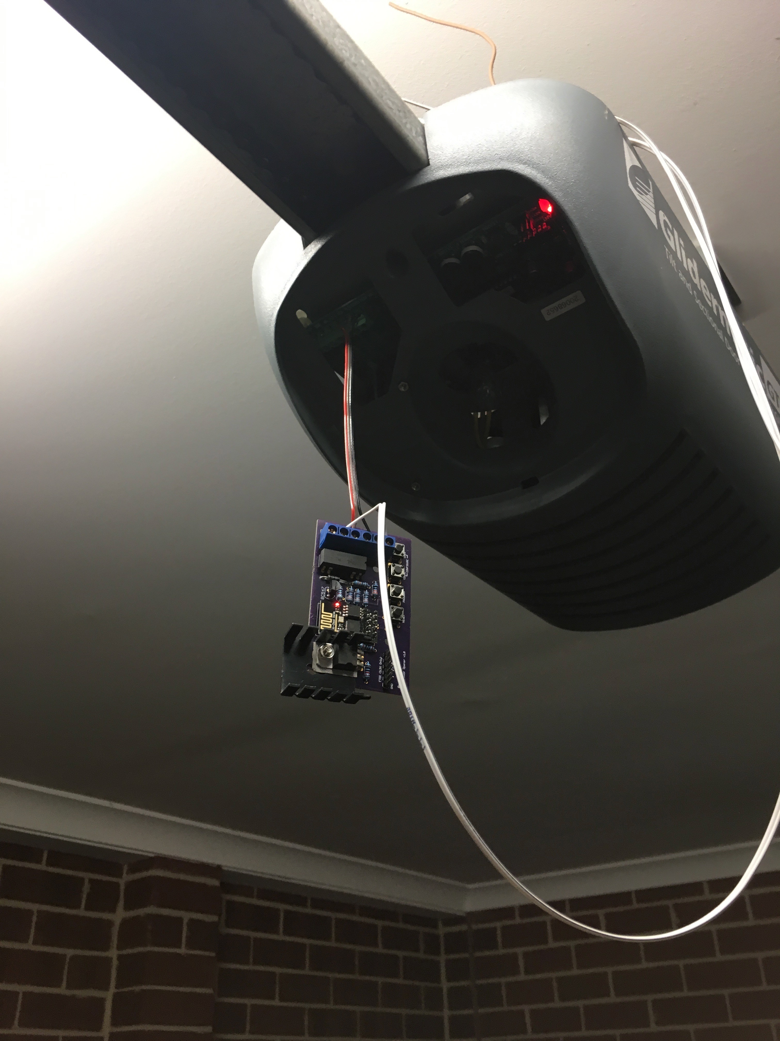
Even though I still have to complete the captivate portal, and over-the-air updates, It seemed like a good time to wire the controller in and see how it all works off the bench.
It’s a good thing I did, as I discovered a few issues with the board.
Excuse the wiring, it’s just temporary…
Originally, I had two switches: one of when the door was completely open, and one for completely closed. Based on the last state, I could guess whether the door was opening or closing. I must admit, I realised long after I ordered and built the board that I really only needed one switch that indicated the closed position. Good thing really, because the device got completely confused after I installed it.
Back story
Because of the limited number of IO pins on the ESP8266-01, I had to pull some tricks to give me two switches and a relay (I can’t take credit, this is an amalgam of a bunch of stuff I found Googling).

There are 4 GPIOs, two of which are shared with the TX and RX pins on the serial port. To make things even more interesting, GPIO0 needs to be held high on boot, otherwise the device goes in to programming mode.
This means GPIO0 is no good as a switch interface – if there was a power outage and the switch attached to GPIO0 was closed as it rebooted, the device would be stuck in program mode.
Conversely, when the device boots up, there is a bit of chatter on TX, so putting the relay on that would be risky – a reboot could cause the door to trigger, and open it when no one was home.
Wiring the relay to GPIO0 and GPIO2 is quite easy, pull them high with pull-up resistors, then switch them to outputs during the setup phase. Setting them both low at the same time sets the relay up. Pulling GPIO2 up, drives the base of a transistor and energises the relay. While the output of the chip could drive the relay directly, I’m actually using a 12v relay that is driven from the convenient 12V output from the garage door controller, so the transistor is required to switch the higher voltage from the lower 3.3V coming out of the regulator.
The “closed” switch is wired to the RX pin, and the “open” switch is wired to the TX pin. This means that the Serial Port is disabled, which can make debugging difficult, so as I work, I usually disable the switches.
This all worked fine on my bench, but as soon as I installed it the close switch wouldn’t register properly, and I couldn’t work out for the life of me why. I suspect the internal state machine wasn’t transitioning properly, possibly because of contact bounce, but it turns out it didn’t matter – I also found what I would call a show stopper: I discovered that if the TX pin was held high (ie the device booted when the door was open) it would never start.
Not ideal.
In a quick refactor of the code, I disabled the state machine, replacing it with a simpler open/close state – if the “closed” switch is closed, the device reports closed, if it’s open, it reports open. Keep it Simple. Who knew, right? Another nice side effect is I can use Serial.println for debugging again. Bonus.
So that brings the mistake count for that board up to four – thankfully all workaroundable (totally a word)fairly easily:
- “Open” switch not needed
- TX and RX pins on the FTDI connector are transposed (fixed by modifying my FTDI cable, which I’m sure will come back to bite me at some point)
- Originally, the GND for both switches shared a screw terminal, although now I can get rid of the open switch, I can keep the board to five screw terminals.
- No room for the heatsink
- (Improvement) Add a jumper to switch between using the 5V off the FTDI cable and an external supply – I was using a fly leads soldered to the bottom of the board while testing.
As a PCB board designer, I’m an excellent software engineer.
Garage Door Opener – Storing the configuration II
I wrote about my “generic” config class in a previous build log, and alluded to how I wasn’t really sure it was the best plan of attack.
It wasn’t.
All of the casting was painful, the setup was annoying and unnecessary (From both a memory and CPU time POV) – there was little (if any) advantage in using it.
In the end, I wrote a concrete class with mutators for each attribute. This meant each attribute is already the correct type, so there was no annoying casting, and I could control and optimise the serialisation and deserialisation.
You can see the class on Github.
The mutators are pretty straight forward, as is the serialisation:
The boolean values (as well as encryption mode and mqtt Auth mode) are compacted using bit-masks, effectively fitting five config items into one byte. Next, I store single integer and double integer values (I use doubles for port numbers), and finally strings.
The strings are encoded by putting their length in the first byte, effectively limiting string length to 255 characters, which is fine – DNS names are limited to this, and that is the biggest thing the config will store. It also makes it possible to avoid overruns, as we have an effective upper limit, so if we go past that index, we know something is broken.
Garage Door Opener – TFW you realise you need a heatsink
Up until now I’ve been testing the door opener using a pigtail off the 5V line on the FTDI cable – the board has a LM317T regulator setup to output the 3.3V that the ESP8266 requires. The installation point for this board is a 12V output from the garage door controller. Those of you with a bit more experience with voltage regulators would realise where this is going… I plugged the board in to a 12V supply and noticed that the regulator was getting really hot.
On my lunch break today, I made my way to Jaycar to grab a heatsink. I was thinking about the little clip on ones, which I looked up on the website while I was on the tram, and I came across “thermal resistance” in the specs.
I had no idea what this was, but I knew that it was probably an interesting specification to look up. After googling it, I discovered it is a measure of how many degrees the heatsink will heat up per watt it is dissipating. Some more googling and I found this page around heatsinking the LM317T, which had all the magic formulas that I needed.
So, the power dissipation is:
P = (Vin – Vout) * I
I had two parts of that equation: Vin = 12V input, and Vout = 3.3V, so I needed to work out the power draw of the ESP8266.
More Googling…
I found these (anecdotal) results, which sounded reasonable. So taking the peak current of 320mA, the power is:
P = (12 – 3.3) * 0.32
P = 2.784W
Apparently, the maximum Thermal Resistance the regulator can tolerate is calculated by:
T(rmax) = (60 – roomtemp) / P
So, let’s make roomtemp = 20 (Yes, I’m in Australia, but I’m also in Melbourne, so that is a good average), giving us:
T(rmax) = (60 – 20) / 2.784
T(rmax) = 14.37 C/W
The little clip on heatsinks have a thermal resistance of 30 C/W, which is double what we need.
Boo.
By this stage I had arrived at the store, so went to the heatsink section to see what they had. They had this guy, which has a thermal resistance of 12 C/W. Perfect! It was quite large though, and I knew they board was tight, so I had to be a little creative in fitting it.
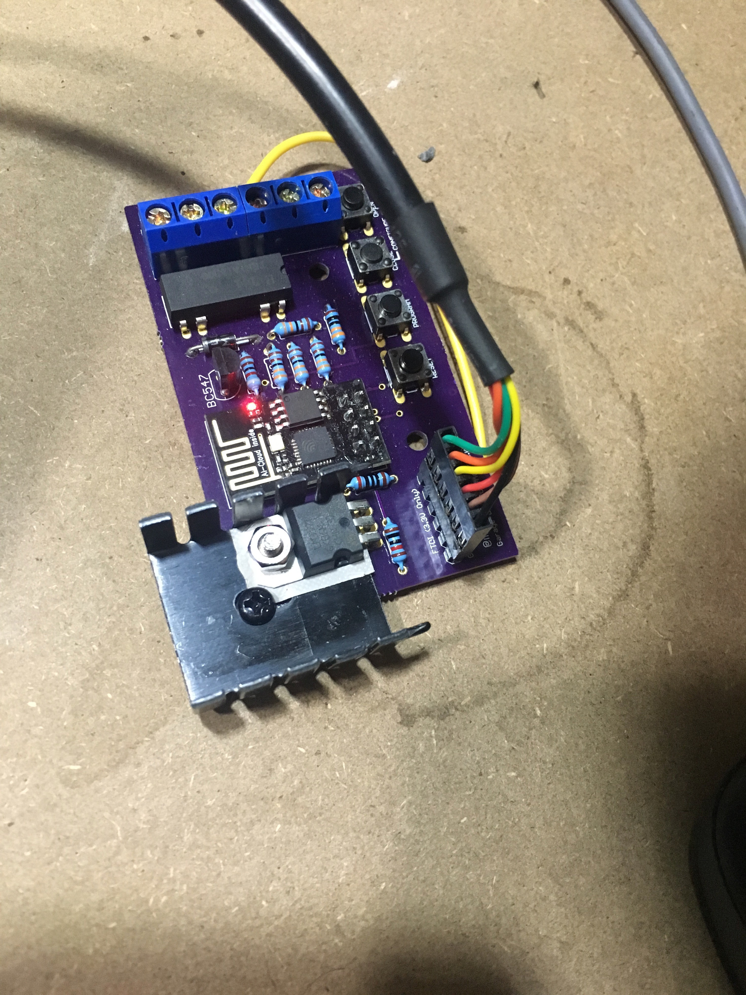
Don’t judge me.
I’m a little annoyed that it doesn’t sit on the board properly, but I couldn’t stand it up, as there was limited room above the board, so it was the best I could do without redesigning an new board.
It’ll do.
Garage Door Opener – Doubling capacity
So, it turns out the ESP8266-01 (at least the one I have) supports 1MB of storage. I had been butting up against the 512kB I thought I had, and it turns out I needn’t worry.
Running this command:
ESP.getFlashChipSizeByChipId()
Will tell you what your chip supports.
This means I can probably incorporate Over-the-air updates, which will be handy. I still need to keep the image under 512kB (OTA needs the space to upload the new image).
w00t!
Garage Door Opener – An mDNS library
I’ve mentioned before that I plan on using mDNS to resolve the name of my server. While the ESP8266 Arduino library can broadcast a mDNS name, it doesn’t query mDNS when resolving names. I found mrdunk’s mdns on Github that implements enough of the mDNS protocol, that I should be able to hack mDNS name queries into the project.
I spun up a quick proof of concept sketch to see how it all works.
// This sketch will display mDNS (multicast DNS) data seen on the network.
#include <ESP8266WiFi.h>
#include "mdns.h"
// When an mDNS packet gets parsed this optional callback gets called once per Query.
// See mdns.h for definition of mdns::Answer.
void answerCallback(const mdns::Answer* answer){
if(strcmp(answer->name_buffer, "mqtt.local") == 0) {
Serial.print("Name: ");
Serial.println(answer->name_buffer);
Serial.print("Answer: ");
Serial.println(answer->rdata_buffer);
Serial.print("TTL: ");
Serial.println(answer->rrttl);
}
}
// Initialise MDns.
// If you don't want the optional callbacks, just provide a NULL pointer as the callback.
mdns::MDns my_mdns(NULL, NULL, answerCallback);
void setup() {
// Open serial communications and wait for port to open:
Serial.begin(115200);
// setting up Station AP
WiFi.begin("[ssid]", "[password]");
Serial.print("Connecting to WiFi");
// Wait for connect to AP
int tries = 0;
while (WiFi.status() != WL_CONNECTED) {
delay(500);
Serial.print(".");
tries++;
if (tries > 30) {
break;
}
}
Serial.println();
}
void query(const char *name) {
mdns::Query q;
int len = strlen(name);
for(int i = 0; i < len; i++) {
q.qname_buffer[i] = name[i];
}
q.qname_buffer[len] = '\0';
q.qtype = 0x01;
q.qclass = 0x01;
q.unicast_response = 0;
q.valid = 0;
my_mdns.Clear();
my_mdns.AddQuery(q);
my_mdns.Send();
}
int send = 0;
void loop() {
if(send == 0) {
query("mqtt.local");
send = 1;
}
my_mdns.Check();
}
The sketch sends a query out for mqtt.local. We are building up a query struct with the requested host name, and a qtype of 0x01 (host address query), and qclass of 0x01 (internet).
When a response is received, the name is checked against the name we requested, and if it matches, the IP address and Time-to-Live (TTL) are printed to the Serial console. The name check is required, because that answerCallback will get called every time a mDNS packet is received, regardless of who sends it – It can get quite chatty.
I found that I needed to call Clear() before adding the query, otherwise the packet was filled with garbage – Clear seems to initialize all the required buffers.
For name resolution, all I really need is the IP address and TTL. My plan is to have an array of names that I need to resolve (for the moment, it’ll be a maximum of two – one for the MQTT server, and one for the log file server). If either of those names end with .local, I’ll resolve the name using mDNS.
On the first request, I’ll cache the result speeding up subsequent requests. I can use the TTL to expire the cached version, and re-query the network when required. A little clunky (it would be nice if the underlying network stack automatically did this), but it should work.
mDNS: A Teardown.
Trying to get mDNS queries working hasn’t quite been as straight forward as I was hoping. I mentioned in a previous log that I found a library, but it was a little overkill for what I need, so I did what any silly software developer does: started rolling my own.
How am I justifying this? Well, I’m fast running out of space. The GitHub version of the ESP8266 hardware definition I’m using is significantly larger than the distributed version, so I only have about 10k of program storage left – as a result I’m being more weary of how much source code I’m uploading. Since I don’t need to respond to mDNS questions (the ESP libs have one built in), I can skip question parsing, and since I’m only interested in name browsing, I can ignore a all bar two classes of responses. And sometimes learning a protocol can be fun. Sometimes.
My completed library can be found here.
The first thing I did was work out how mDNS works. It’s a pretty clever hack – It reuses standard DNS packets, but rather than ask a specific DNS server to answer a query, mDNS clients just broadcast a UDP packet to anyone who will listen. If another listener can answer the question, it broadcasts the answer. You can see more information about the packet format on the mDNS Wikipedia page.
Looking at the packet structure, and looking through the code from this mrdunk’s library, as well as some packet sniffing using wireshark, I was able to generate questions and parse answers. This was very much proof of concept code that was embedded in my project, and it worked, though it lacked formal testing, and this would definitely be something I would want to reuse in the future.
ime to break it out in to another library.
Now, my C++ isn’t particularly strong, so this sounded like a good opportunity to learn more about C++ classes. I had a niggling concern around code size, memory usage and speed when it came to using C++ for embedded systems, so I did a bit of research around best practices, and found this article. What I found particularly useful in the article was the explanation of how C++ achieves what is does in terms of the equivalent C code. This clicked in to place what C++ was doing and allowed me to make some better decisions around structuring my library. Though I did get tripped up. A lot
The basic rules are:
- Don’t use exceptions (you can’t on Arduino), so most functions return a status code indicating success or error states.
- Avoid virtual functions where possible, because you end up with a vtable which takes up memory and requires extra cycles to lookup where the address of the required function
- Avoid dynamic memory
- If you need dynamic memory, free it as soon as possible, or make it super long living to avoid fragmentation
- Don’t include unnecessary libraries. I thought I would do the right thing and use std::string which abstracts string handling. This made my library’s object file an order of magnitude larger. Reverting back to regular char* string keped everything nice and small, and as I didn’t need to do much actual string manipulation, the trade of was totally worth it.
Testing
I’m a big believer in automated testing. Especially for something as low level as a library where you rely on certain types of network packets. Automated testing on an Arduino is probably possible, but since I’m not doing anything too Arduino specific, I was able to build a test suite that ran on my laptop. This made the test cycle much quicker as I didn’t have to wait for my code to upload. The downside is I need to mock out a few objects, but with some clever code organisation I managed to avoid too many mocks.
I found Catch which is a header-only, lightweight testing framework for C++. It was pretty easy to setup, and works with TravisCI, so every time I commit a change the tests run automatically.
Travis was a bit of a pain to setup, as the C++ they run is ancient, so I needed to setup a custom toolchain in travis.yml.
Once I had everything written and tested, I was able to drop it in to the Garagedoor sketch, and now the sketch can find the mqtt server!
Garage Door Opener – So, the ESP8266 does support TLSv1.2
I was digging around the ESP8266 github page, as there was an announcement that it now supports CA verification (it ALMOST does – there was a regression bug that means it’s still not working), but I noticed that the last release (2.3.0 at time of writing) is actually quite old – it was released in June.
I was going through recent commit messages, and noticed there had been quite a bit of work around integrating axTLS, which is a tiny TLS library specifically designed for computers with small memory footprints (AKA microcontrollers).
This piqued my interest.
It has been said that the ESP8266 doesn’t support TLSv1.2, because of a buggy implementation in the firmware, which I had verified earlier in testing and hence configuring MQTT to force TLSv1.1.
By including axTLS as part of the Arduino library, and not relying on the ESP8266 API, I wondered if TLS1.2 was now supported.
Turns out it is!
It does mean we’ll have to use a “unstable” version of ESP8266 library. This means other stuff might not work, we need to install it using git, and it’s up to us to keep everything up to day.
Thankfully, it isn’t that difficult to install the library using git.
First, remove the existing ESP8266 library using the board manager – find it using the search function, then hit remove.
Now, you can manually install – Instructions are here. Don’t forget to re-select the right board and to set the CPU frequency to 160Mhz!
Now, that regression bug. It stops client certificates being sent for verification, which is bad for us, so we’ll need to roll back a couple of commits. To do that:
cd ~/Arduino/hardware/esp8266com/esp8266
git checkout -b pre-axtls-2 d6e38f0abd2e1bf796a32e8b1a24d37fdc7daaf8
This creates a new branch based on an older revision that seems to still work ok.
Modify mosquitto to use TLSv1.2
This one’s pretty easy: Remove the tls_version line
#tls_version tlsv1.1
Then remove
"--tls-version", "tlsv1.1",
from both mosquitto-client/Dockerfile.pub and mosquitto-client/Dockerfile.sub.
Run
docker-compose build
and start the server with
docker-compose up
You should see “Hello world” in there somewhere. Next up, the Arduino side of things…
Garage Door Opener – Adding TLS
While having a username and password is better than an open MQTT server, the credentials are still being sent in plain text, so anyone with a packet sniffer could intercept them and then gain access to our server.
To avoid this, let’s setup TLS (commonly, but maybe not correctly known as SSL) to encrypt the connection and kept the credentials secret.
TLS 101
TLS provides a chain of trust, allowing two computers that know nothing about each other to trust each other.
Let’s look at how this works in the context of a browser hitting a secure website, as this is an example we should all be familiar with.
At a really high level, both your computer and the server have a Certificate Authority (CA) that they both implicitly trust (there is actually more than one, but let’s keep it simple). When you hit a website that is secured the server sends it’s certificate to the browser, which does some complicated maths and verifies the certificate against the CA – if the numbers work out, your browser can be confident that the certificate is legitimate and that the secure site is who it says it is.
Web servers generally don’t care who the client is, so they rarely ask for a client certificate, but in other applications (like this garage door opener) the server will also verify the client against it’s CAs.
After both computers are happy they are talking to the right people, they will exchange a set of symmetric keys that both computers will use to communicate. Symmetric keys are much faster to encrypt and decrypt that asymmetric keys, but it requires both sides to have the same key.
To do that securely, a symmetric key is generated, encrypted using the other computer’s public key, sent securely across the wire and then decrypted – now both computers have the key and they can start talking.
Setting up our own trust network
Enough theory! The first thing to do is generate a CA. If you have OpenSSL installed on your computer (Linux and OSX users more than likely will), you can generate a CA on the command line:
openssl req -new -x509 -days 3650 -extensions v3_ca -keyout ca.key.pem -out ca.crt.pem
You’ll be asked for a PEM password – make this something difficult to guess and then store it in your password manager.
This is literally the key to the city. If someone gets hold of your ca.crt.pem and ca.key.pem, and can guess your password, then they can generate their own valid certificates – not good. Fill in the details as you are asked – these details aren’t super important as this is a personal CA, but make the values something you will recognise. The common name can be whatever you want. Now that you have your CA certificate (ca.crt.pem) and your CA.key (ca.key.pem) you can generate some certificates.
An aside: If you have a password manager that supports notes, I’d recommend saving these files in the there and deleting them from your file system after you have generated any certificates that you need.
Generate a server certificate
For this to work, it’s best to use actual domain names for servers and clients – the easiest way to do this is setting up mDNS, via avahi (linux) or bonjour (OSX) – Windows probably has something too – let’s assume that the name of the computer running MQTT is mqtt.local and the name of the garage door opener will be garage.local.
# Generate a key
openssl genrsa -out mqtt.local.key.pem 2048
# Create a Certificate signing request
openssl req -out mqtt.local.csr.pem -key mqtt.local.key.pem -new
Again, fill in the details as you are asked.
The MOST important one is Common Name. IT MUST MATCH THE DOMAIN. So in our case: mqtt.local
# Sign the certificate
openssl x509 -req -in mqtt.local.csr.pem -CA ca.crt.pem -CAkey ca.key.pem -CAcreateserial -out mqtt.local.crt.pem -days 365
You will be asked for the password you entered when you created your CA.
Note that the certificate is valid for 365 days – you’ll have to generate a new one in a years time. You can decide if you want to make it longer or shorter.
Generate the client certificate
Generating a client certificate looks a lot like the generation of a server certificate – just with different filenames.
# Generate a key
openssl genrsa -out garage.local.key.pem 2048
# Create a Certificate signing request
openssl req -out garage.local.csr.pem -key garage.local.key.pem -new
The common name this time should be garage.local
# Sign the certificate
openssl x509 -req -in garage.local.csr.pem -CA ca.crt.pem -CAkey ca.key.pem -CAcreateserial -out garage.local.crt.pem -days 365
Setting up Mosquitto
Now we have all of the certificates that we need, let’s setup mosquitto to use it.
Create a ca_certificates and certs directory in the mosquitto/etc docker folder
mkdir mosquitto/etc/ca_certificates
mkdir mosquitto/etc/certs
and copy ca.crt.pem to the ca_certificates folder and mqtt.local.crt.pem and mqtt.local.key.pem to the certs folder. Finally update the etc/mosquitto.conf file to look something like this:
persistence true
persistence_location /var/lib/mosquitto/
password_file /etc/mosquitto/passwd
allow_anonymous false
cafile /etc/mosquitto/ca_certificates/ca.crt.pem
certfile /etc/mosquitto/certs/mqtt.local.crt.pem
keyfile /etc/mosquitto/certs/mqtt.local.key.pem
port 8883
tls_version tlsv1.1
include_dir /etc/mosquitto/conf.d
Notice we have changed the port to 8883, which is the standard port for secure MQTT. We are also still authenticating via username and password.
We are explicitly forcing TLS version 1.1 because the ESP8266 implementation of 1.2 is buggy, and will fail.
Save the file, and run
docker-compose build mosquitto
Because we aren’t verifying the certificates, we can use the garage.local certificate on the command line to test everything out.
Create the ca_certificates and certs directories, this time in mosquitto-client
mkdir mosquitto-client/ca_certificates
mkdir mosquitto-client/certs
Copy ca.crt.pem to the ca_certifications directory and both the garage.local.crt.pem and garage.local.key.pem files to the certs directory.
Now, modify the Dockerfile.sub ENTRYPOINT to look like this:
ENTRYPOINT [ "mosquitto_sub", "-h", "mosquitto", "-p", "8883", "--tls-version", "tlsv1.1", "--cafile", "/ca_certificates/ca.crt.pem", "--insecure", "--cert", "/certs/garage.local.crt.pem", "--key", "/certs/garage.local.key.pem" ]
and the Dockerfile.pub ENTRYPOINT to look like:
ENTRYPOINT [ "mosquitto_pub", "-h", "mosquitto", "-p", "8883", "--tls-version", "tlsv1.1", "--cafile", "/ca_certificates/ca.crt.pem", "--insecure", "--cert", "/certs/garage.local.crt.pem", "--key", "/certs/garage.local.key.pem" ]
Finally, run
docker-compose build
and
docker-compose up
And everything should connect again, but this time securely!
All of these instructions gratuitously stolen from: https://mosquitto.org/man/mosquitto-tls-7.html
Garage Door Opener – Using a username and password for MQTT
Now we have the ESP8266 talking to the MQTT broker, let’s have a look at adding some authentication. The simplest form of authentication is a username and password, which Mosquitto supports. It uses a password file that has a list of all the usernames allowed to login as well as hashes of their passwords.
We will need to create a configuration file to tell mosquitto where to find that file – create an etc directory in the mosquitto directory that is in the root of the docker project:
mkdir mosquitto/etc
create a file called passwd and enter the following:
password_file /etc/mosquitto/passwd
allow_anonymous false
We are simply telling Mosquitto to
- look for the passwd file in /etc/mosquitto, and
- we only want to allow users that have authenticated.
Next, let’s use docker to run the mosquitto_passwd command
docker-compose mosquitto run /bin/bash -c "touch /tmp/passwd && mosquitto_passwd -b /tmp/passwd [username] [password] && cat /tmp/passwd && rm /tmp/passwd" > mosquitto/etc/passwd
Let’s break that monstrosity down.
Since we haven’t set up a docker volume, we can’t easily fetch the file from the container, so instead we run bash and pass it a mini script that:
- creates a temporary passwd file,
- runs mosquitto_passwd (Don’t forget to change [username] and [password] to real values),
- prints out the file, then
- deletes the temporary file.
- Finally, (back on the host computer) we pipe the result in to a file mosquotto/etc/passwd.
If that worked, you should see a new file called passwd in the mosquitto/etc folder.
Next, we need to tell docker to copy our new config file and password file into the container when it builds. Open mosquitto/Dockerfile and add the following lines before the EXPOSE command
COPY ./etc/mosquitto.conf /etc/mosquitto/mosquitto.conf
COPY ./etc/passwd /etc/mosquitto/passwd
We should also update the client containers so they can login when we bring docker-compose up
The ENTRYPOINT line should like this for mosquitto-client/Dockerfile.pub
ENTRYPOINT [ "mosquitto_pub", "-h", "mosquitto", "-u", "[username]", "-P", "[password]" ]
and for mosquitto-client/Dockerfile.sub
ENTRYPOINT [ "mosquitto_sub", "-h", "mosquitto", "-u", "[username]", "-P", "[password]" ]
Those are capital Ps – and don’t forget to update [username] and [password] to match the values you saved in the passwd file!
Rebuild, and run docker, and you should see the two clients successfully connect, and “Hello World” being printed to the console.
docker-compose build
docker-compose run
Setup Ardiuno
This is a fairly easy modification. Find the line that looks like:
if(!pubSubClient.connect(MQTT_NAME)) {
and change it to
if(!pubSubClient.connect(MQTT_NAME, "[username]", "[password]")) {
Push the code to the ESP8266, run it, and you should see it connect just like it did before! Except this time, it will be using a username and password.You can verify that by using an incorrect username or password – the ESP8266 will never be able to connect.
Garage Door Opener – Let’s connect
So, now we have an MQTT server, lets see if we can get the ESP8266 to connect to it.
I’m going to use Nick O’Leary’s pubsubclient library. It’s pretty easy to install – find Manage Libraries in the Sketch Menu, search for pubsubclient and it should appear. Hit install.
After we physically connected to the WIFI (Which we’ll do via via hard coding the SSID and passkey for the moment – we’ll do that properly later), there are two things we need to do:
- Connect to the MQTT server – no security for the moment, we’ll work up to that
- Subscribe to a message. We provide the library with a callback function that gets called every time the server receives a message topic that we are subscribed to.
Here is the some proof of concept code that does all of that:
#include <ESP8266WiFi.h>
#include <ESP8266mDNS.h>
#include <PubSubClient.h>
#define SSID "your-wifi-ssid"
#define PASSKEY "your-wifi-password"
#define MQTT_IP "ip-address-of-the-mqtt-server"
#define MQTT_PORT 1883
#define MQTT_NAME "garage"
#define TOPIC "test"
#define QOS_LEVEL 0
// PubSub client
WiFiClient espClient;
PubSubClient pubSubClient(espClient);
void PubSubCallback(char* topic, byte* payload, unsigned int length);
long lastPubSubConnectionAttempt = 0;
void PubSubSetup() {
pubSubClient.setServer(MQTT_IP, MQTT_PORT);
pubSubClient.setCallback(PubSubCallback);
}
boolean PubSubConnect() {
Serial.print("Connecting to MQTT server...");
if(!pubSubClient.connect(MQTT_NAME)) {
Serial.println("\nCouldn't connect to MQTT server. Will try again in 5 seconds.");
return false;
}
if(!pubSubClient.subscribe(TOPIC, QOS_LEVEL)) {
Serial.print("\nUnable to subscribe to ");
Serial.println(TOPIC);
pubSubClient.disconnect();
return false;
}
Serial.println(" Connected.");
return true;
}
void PubSubLoop() {
if(!pubSubClient.connected()) {
long now = millis();
if(now - lastPubSubConnectionAttempt > 5000) {
lastPubSubConnectionAttempt = now;
if(PubSubConnect()) {
lastPubSubConnectionAttempt = 0;
}
}
} else {
pubSubClient.loop();
}
}
void PubSubCallback(char* topic, byte* payload, unsigned int length) {
char *p = (char *)malloc((length + 1) * sizeof(char *));
strncpy(p, (char *)payload, length);
p[length] = '\0';
Serial.print("Message received: ");
Serial.print(topic);
Serial.print(" - ");
Serial.println(p);
free(p);
}
void connectWifi(const char* ssid, const char* password) {
int WiFiCounter = 0;
// We start by connecting to a WiFi network
Serial.print("Connecting to ");
Serial.println(ssid);
WiFi.disconnect();
WiFi.mode(WIFI_STA);
WiFi.begin(ssid, password);
while (WiFi.status() != WL_CONNECTED && WiFiCounter &amp;lt; 30) {
delay(1000);
WiFiCounter++;
Serial.print(".");
}
Serial.println("");
Serial.println("WiFi connected");
Serial.print("IP address: ");
Serial.println(WiFi.localIP());
}
void setup() {
Serial.begin(115200);
connectWifi(SSID, PASSKEY);
PubSubSetup();
}
void loop() {
PubSubLoop();
}
To run this, first fire up our MQTT server using docker-compose up, next load up the above code on the ESP8266, replacing the constants at the top of the file with the relevant settings.
If you are running Docker on Linux, or using Docker for Mac; or Docker for Windows the IP address of the server will be the same as the IP address of your computer.
If you are running docker-machine, you will need to run docker-machine ip to find out the local IP address.
Open up the serial monitor and you should see something like this:
Connecting to [what ever your ssid is].
WiFi connected
IP address: [some IP address]
Connecting to MQTT server... Connected.
Now, if we publish a message on to the queue
docker-compose run mosquitto-publisher -t "test" -m "Hello Arduino!"
We should see the Arduino consuming the message:
Message received: test - Hello Arduino!
If you don’t see the message, there should be hints in the serial monitor about what went wrong.
Things to look out for:
- If you can’t connect to the WiFI, check your SSID and passkey
- If you can’t connect to the MQTT server, check your IP address. Also, check the docker output – you should see a message when the Arduino connects.