Garage Door Opener – How can I make this garage door opener secure?
One of the design goals for this project was a secure system – this device can open my garage, and I don’t really want just any person to be able to do that!
Disclaimer: I’m not a security expert! If you find holes in my logic, please let me know!
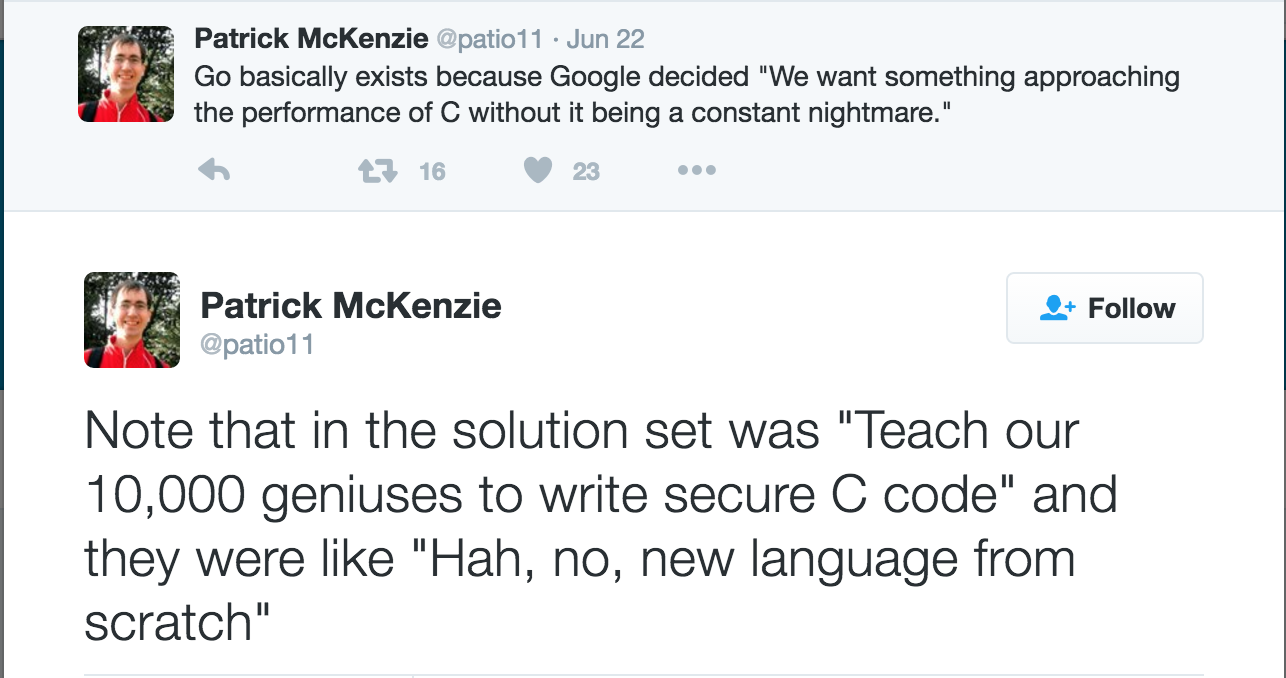
The most obvious way to interface with the controller was to setup some sort of server that a controller (eg an iPhone app) talks to. The problem with this is that an open network port is an attack vector – if a good guy can connect to a network port, so can a bad guy. While I could set up a username or password, having a port open potentially means buffer overflows, and since I’m not really a C/C++ guy this a big problem for me – I mean a lot of really smart people avoid writing servers in C…
After some research, I found this paper (PDF) talking about the use of the publish/subscriber pattern (AKA pub/sub), where a device connects to as server and subscribes to event notifications. This means there is no port open on the device, so even if an attacker found it’s IP address, there is no way for them to connect to it. It seems MQTT is the IOT pub/sub system of choice (it drives a lot of public IOT platforms).
This of course is not without other issues (not exhaustive – please suggest more if you can think of others):
- Problem: If an attacker got on the network, they could just connect to the MQTT server and send a “open” command. Solution: Access control lists (ACL): Only allow certain MQTT clients send certain commands. We would need some way for the server to verify who the client is…
- Problem: What if an attacker managed to spoof the IP or MAC address (perhaps through ARP poisoning) they could become a legitimate MQTT server, allowing them to send an open command. Solution: Verify the identity of the server. TLS certificates can help with that. Using a certificate signed by a custom Certificate Authority (CA) means we can guarantee the server is who it says it is. This also fixes the client verification problem from point 1.
After a quick search, I found the mosquitto project – an open source MQTT server which looked pretty easy to setup, supports ACLs and TLS.
Docker all the things
I decided to set it up a test environment using docker, as it makes dependency management much easier, and also makes the setup scriptable, so when it comes time to deploy to “production” I know exactly what I need to do.
You can clone my git repository to get started (I’ve tagged each of the steps so you can play at home – we’ll start with mqtt-1):
git clone https://github.com/madpilot/home-automation
cd home-automation
git checkout -b mqtt-1 mqtt-1
docker-compose build
docker-compose up
Congratulations! You now have a working MQTT server running on port 1883. Because it hasn’t configured it yet, the server has no authentication or authorisation – that’s fine for the moment – let’s get the baseline working, then we can add the security layers later.The easiest way to test the server is to use the mosquitto command line client. I’ve included these as part of the docker-compose cluster – in fact, when you ran docker-compose, a subscriber was automatically created (subscribed to the “test” channel) and publisher publishes the first message.
Look through the output on the screen. If you see:
mosquitto-subscriber_1 | Hello World
Everything has worked!You can try it out yourself – run the following command:
docker-compose run mosquitto-publisher -t "test" -m "Hello again"
And you should see
mosquitto-subscriber_1 | Hello again
I’ve been a bit tricky by using a docker entry point to hide away the full command to make sending messages much easier. The full command that gets called is
mosquitto_pub -h mosquitto -t test -m "Hello again"
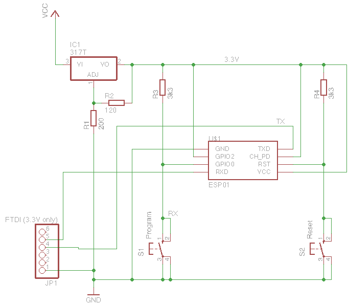
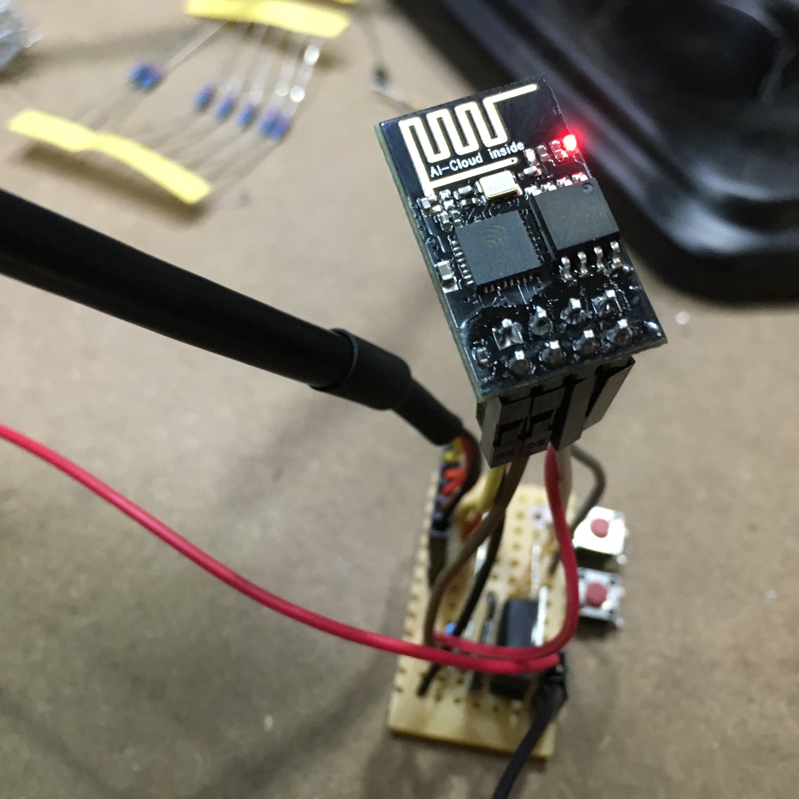
Which tells mosquittopub to connect to the server with a host name of _mosquitto (Which is set by docker), publish to the “test” channel, and send the message “Hello again”.Now that we have a working MQTT server and a way of testing things, we can start looking at the Arduino side of things.