@madpilot makes

Reverse engineering a Fujitsu Air Conditioner Unit – Baseline communication

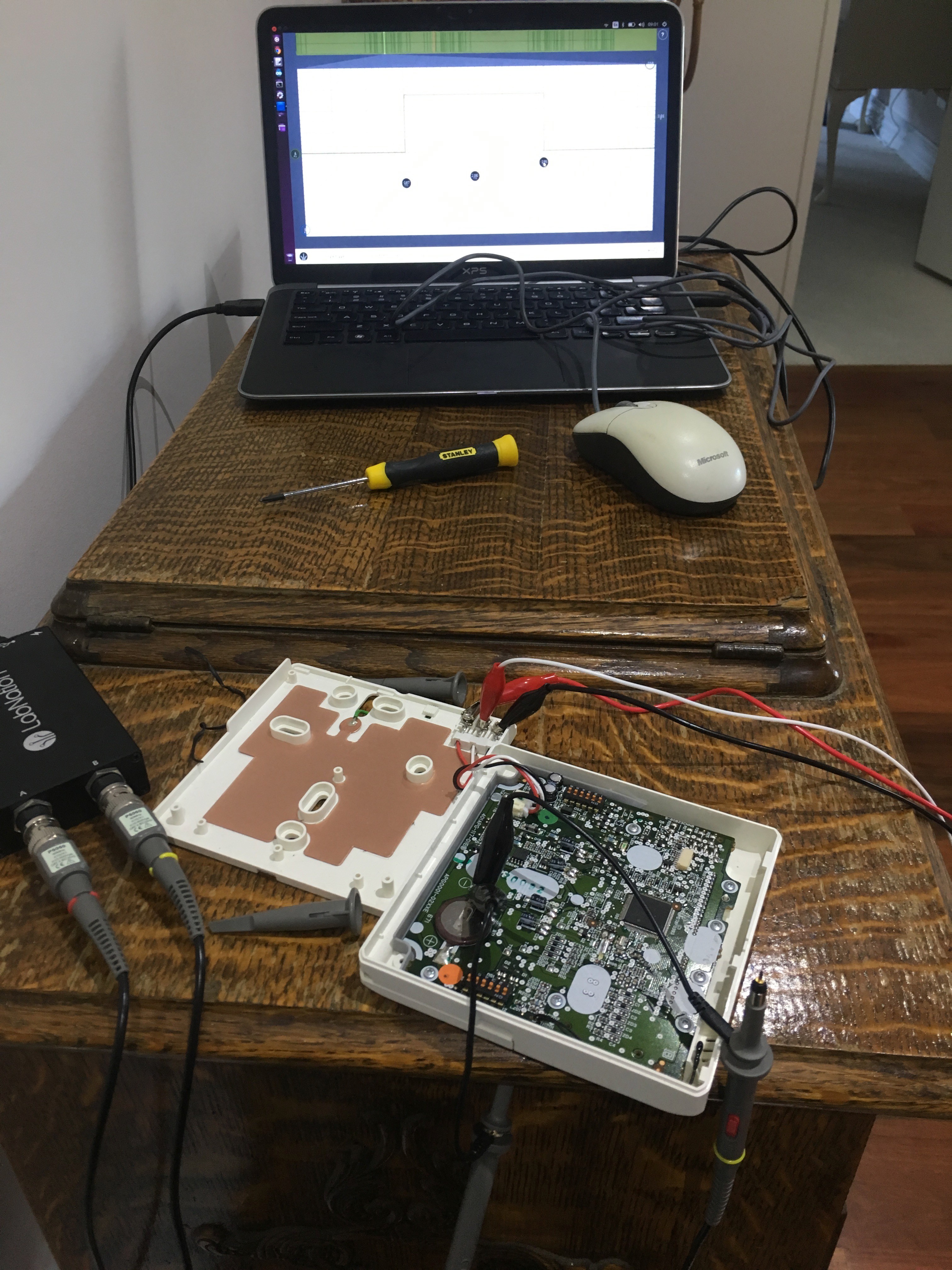
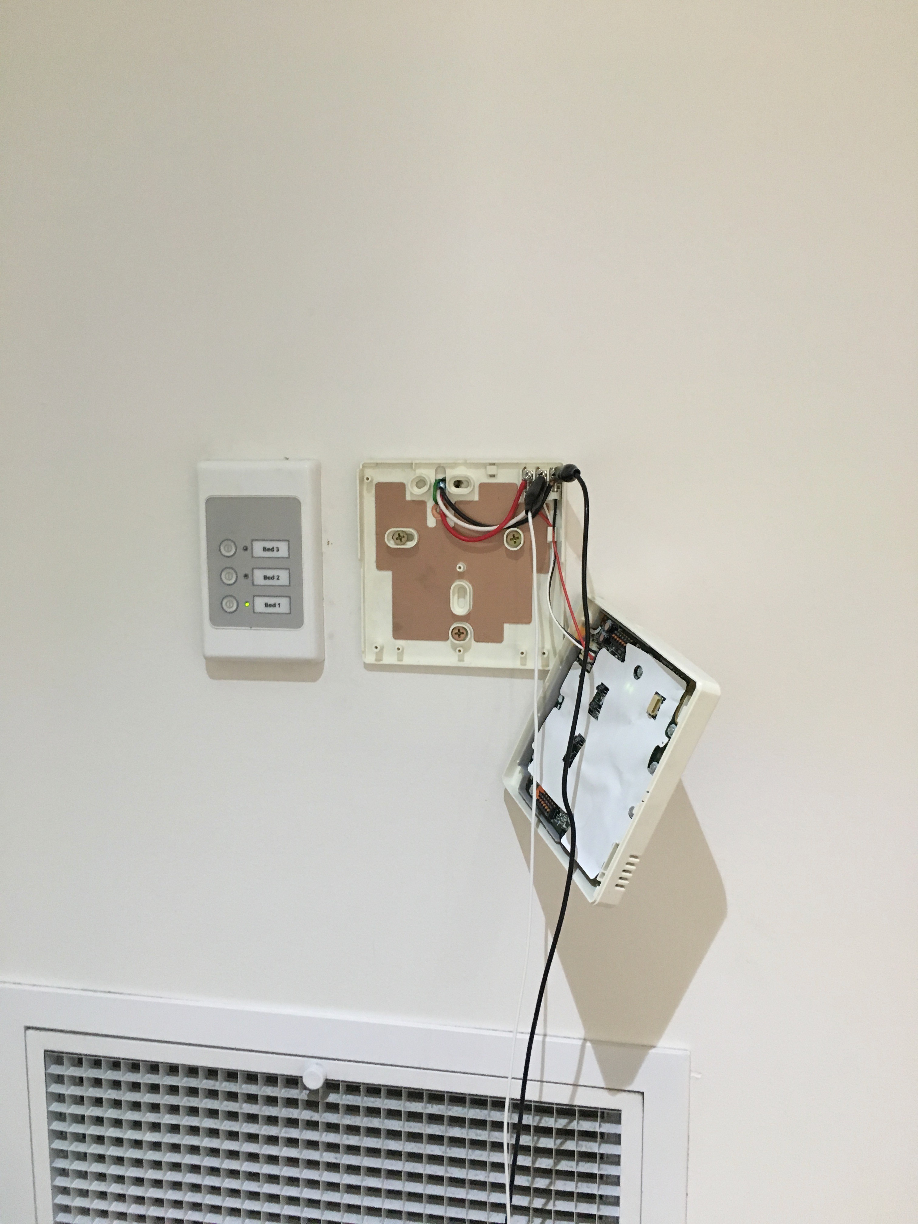
I took the remote unit off the wall again, and this time removed the signal wire fro the remote and attached it to my Oscilloscope.

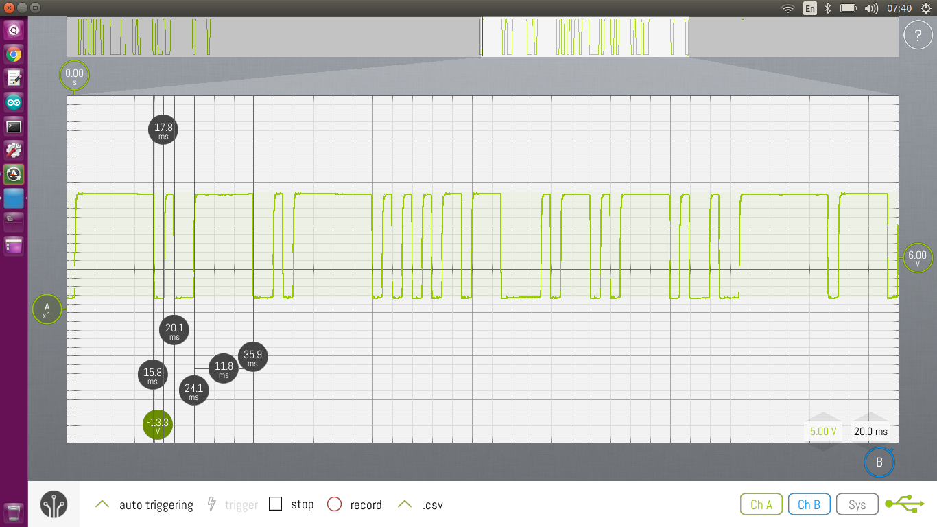
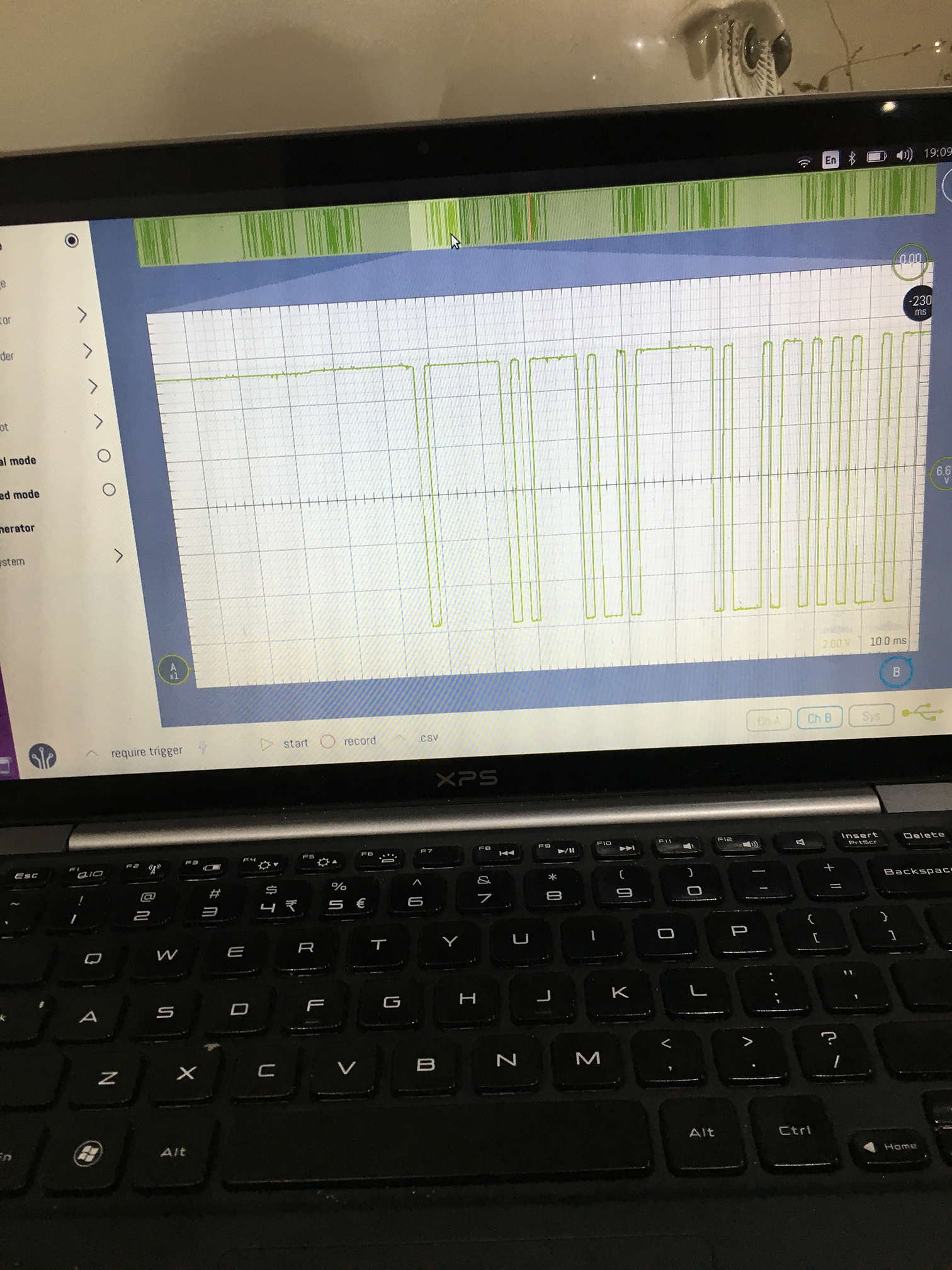
And this is signal that comes from the outdoor unit.

I’m not sure if I stuffed up my reading the last time, but it looks like the pulse width is 2ms.

Really, I needed to replay this and see if I could get my test unit to initialise. I thought about using an Ardiuno, so I googled bit banging serial to see the best way to do it. One of the results that caught my eye was another Hackaday article entitled “Introduction to FTDI bitbang mode“. I had literally just cleaned up my workbench and found a FTDI module. Perfect!

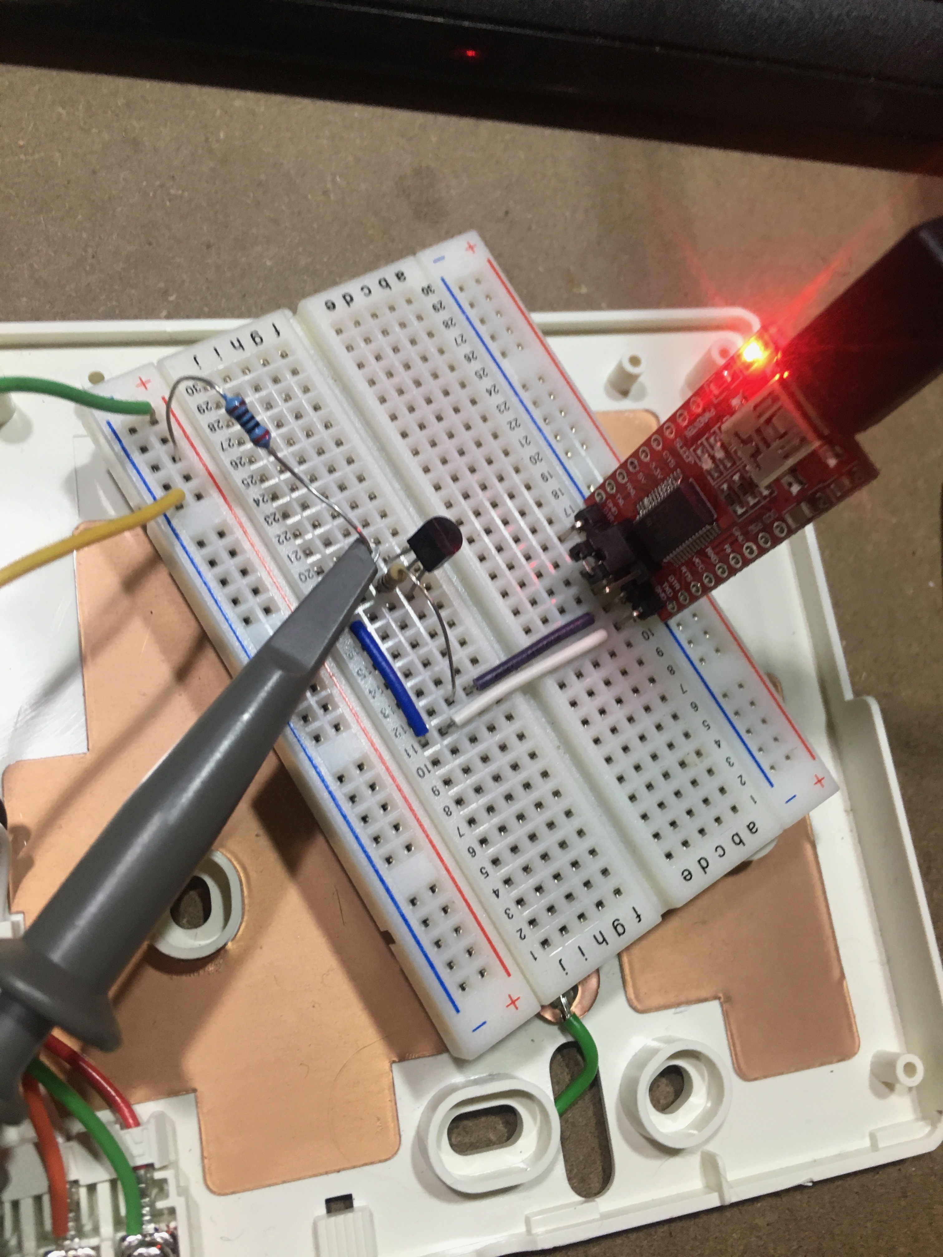
I knocked up a little circuit that drove a transistor from 0V to 12V, and adapted the code from the article to control the FTDI modules CTS line. I had to reduce the sleep time to 1.8ms to adjust for kernel context switches (I’m guessing) while talking to the adapter. I got it pretty close to 2ms though.

I wired it up to the controller, and got one step closer – now instead of timing out and flashing C0 12, it just sits flashing “9C” forever.

My guess? This communication protocol works on one-wire – I’m not releasing the line, so the remote never gets a chance to send a response. It looks like I’ll need some sort of tri-state buffer, so I can set the line to high-impedance after I’ve sent the preamble.

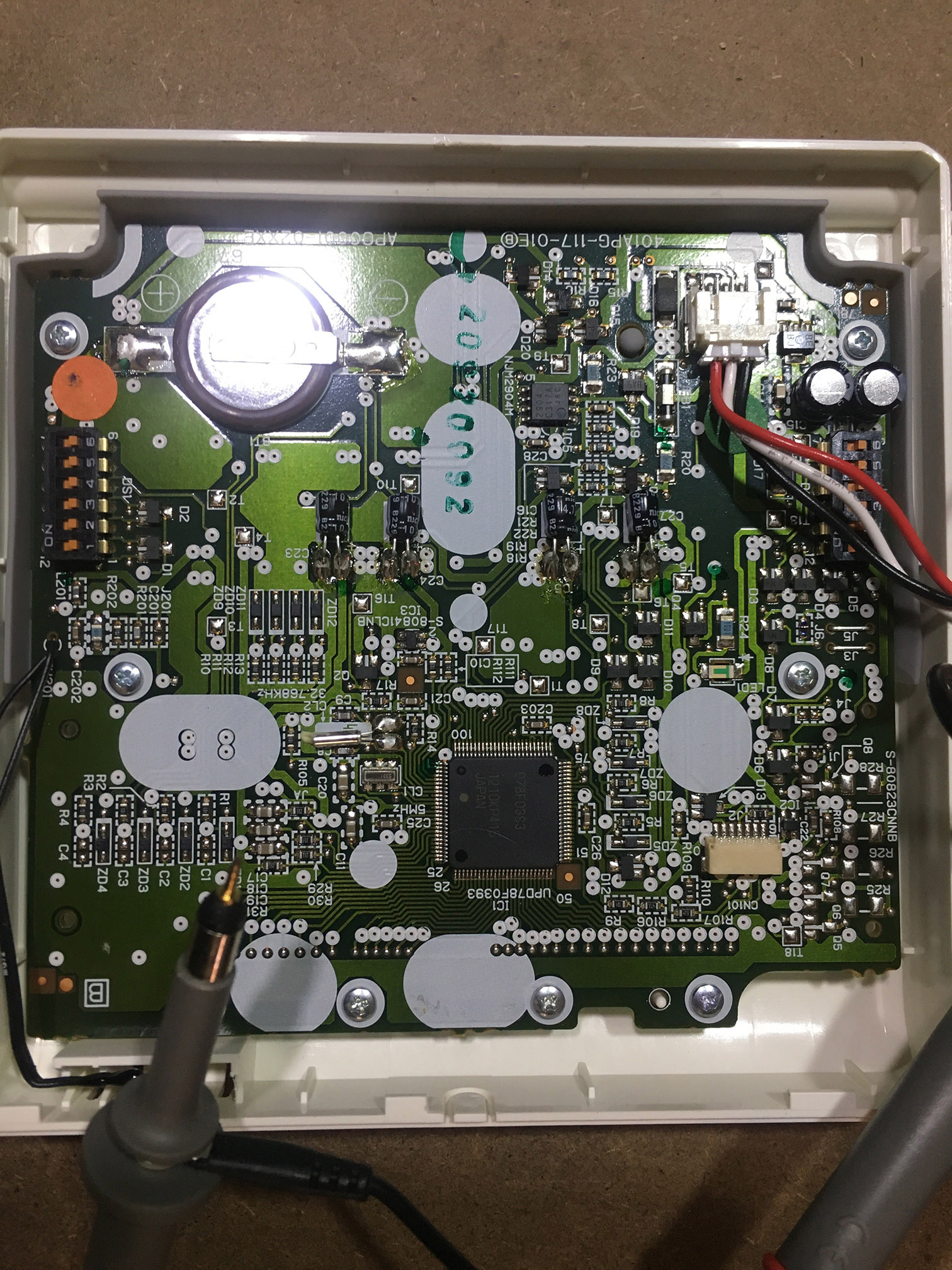
I was curious to see if I could get any other clues to the protocol, so I started poking around the big chip on the PCB. One of the pins receives the same signal the signal line does, except it’s inveted and 0-5V! I went and looked up the chip (it’s a UPD78F0393 from NEC – I’m so glad the remote manufacture labelled all their chips nicely), and that pin (#75) is labelled RXD0. That sounds like a serial receive line to me!

Pin 76 is labelled TXD0, which I’m guessing is the transmit line. This should make decoding stuff way easier, because I’ll be able to see what is actually being transmitted and received separately. Win!

I’m going to try and trace out the front-end to this – so far I see a NJM2904 (an op-amp) is on the path – my guess is that is the thing inverting the signal and driving it to 12V. Tracing this circuit out should allow me to build a compatible circuit from my microcontroller.

Reverse engineering a Fujitsu Air Conditioner Unit – A test unit arrives

So my test unit arrived!

I get it on my bench, and test out my theory – if I’m right, it should boot up and start sending commands when the buttons are pressed.

I was wrong.

The unit just sits there flashing “9C” for a couple of minutes, then failing over to a “C0 12” error. The Oscilloscope was no use either – I just saw a constant 12V on the signal wire.

Hmmm.

Looks like I’ll have to pull off the real wall unit.

Using some wire and alligator clips, I extended the wires so I could reach them with the scope.

This time I got somewhere – I could see a signal!

The pulse width is around 1.04ms, going from 12V to 0V. Weird.

I go distracted for a while trying to decode the protocol – is there start bits and stop bits? What about a parity bit?

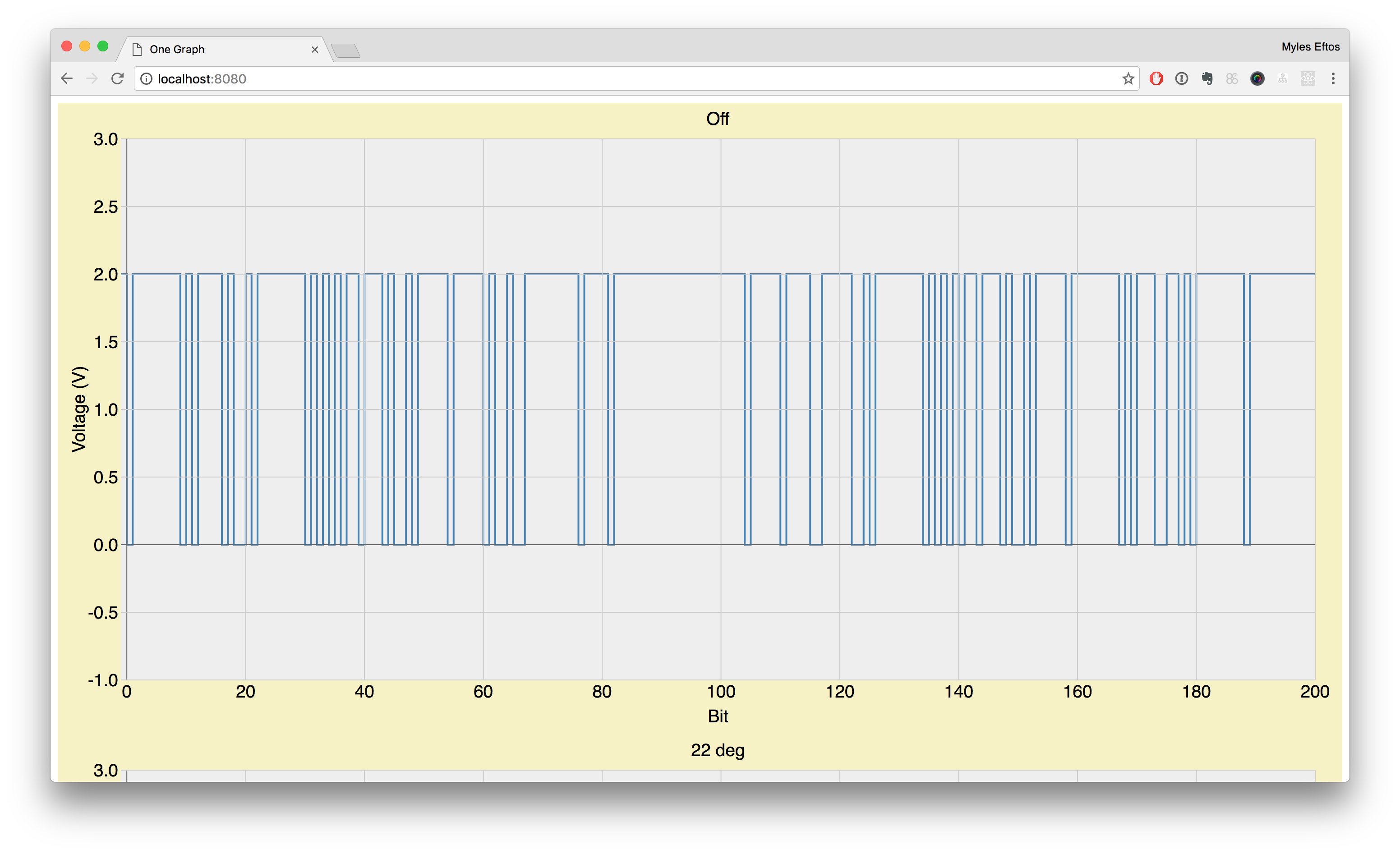
I knocked together a quick D3 script (I’m a web developer, remember – I use web technology for a lot of this stuff because that is what I’m used to) to display the wave form. First, I wrote a ruby script that created a CSV file of just the transitions. There are two entries for each transition – a 0V and 12V value – so the graph ends up looking like a binary stream.

I then wrote another script that aligned the stream so each pulse was exactly 1.04, and each pulse hight was 12V or 0v. Finally, I scaled everything so the pulse width was 1, as this made reading the graphs easier.

I ended up with some pretty graphs like this:

There was still a problem though – I didn’t have a baseline for the communications.

I knew that the control unit didn’t send any data unless it was connected to the outside unit. I also knew that changing the temperature changed some of the bits in the data stream, so clearly there was some half-duplex serial communication going on. I needed to find out what the outdoor unit sent to initialise the control unit…

Reverse engineering an air-conditioner remote – How does this thing work?

I’ve never done any reverse engineering before, but spurred on by this recent Hackaday article, and this article I found I thought I’d give is a crack.

The first issue: I had no idea what the model number was – it’s not written on the unit, nor on the instruction manual. So I just googled for Fujitsu airconditioner remote, hit image results and looked for one that looked the same. Once I found it and clicked through to the source page, I found out that it is a UTB-YUB/GUB/TUB (There are three model numbers depending on where in the world you are).

I found a supplier on ebay (who was actually Melbourne based), who had a new remote unit for $60, which I bought as I wanted a test unit on my workbench – mainly because trying to test things using the unit on the wall would be really annoying.

While I waited for it to arrive, I continued googling to find as much info as I could about it. Thankfully, a number of airconditioning repair places have their installation manuals online. Reading though the them, it was clear there was a three wires that connect the remote to the outdoor unit – +12V, GND and a signal.

Bingo.

Now, I need to work out what this signal wire does.

My first hypothesis was the remote unit worked a lot like an IR remote – every button press sent the complete state to the outdoor unit. If this was the case, it should just be a matter of hooking up a DSO (I have the LabNation SmartScope), copying the signal and replaying it via a microcontroller.

While I could pull the one off the wall, I patiently waited for my test unit to arrive.

IR-blaster with CEC – The IR Blaster circuit

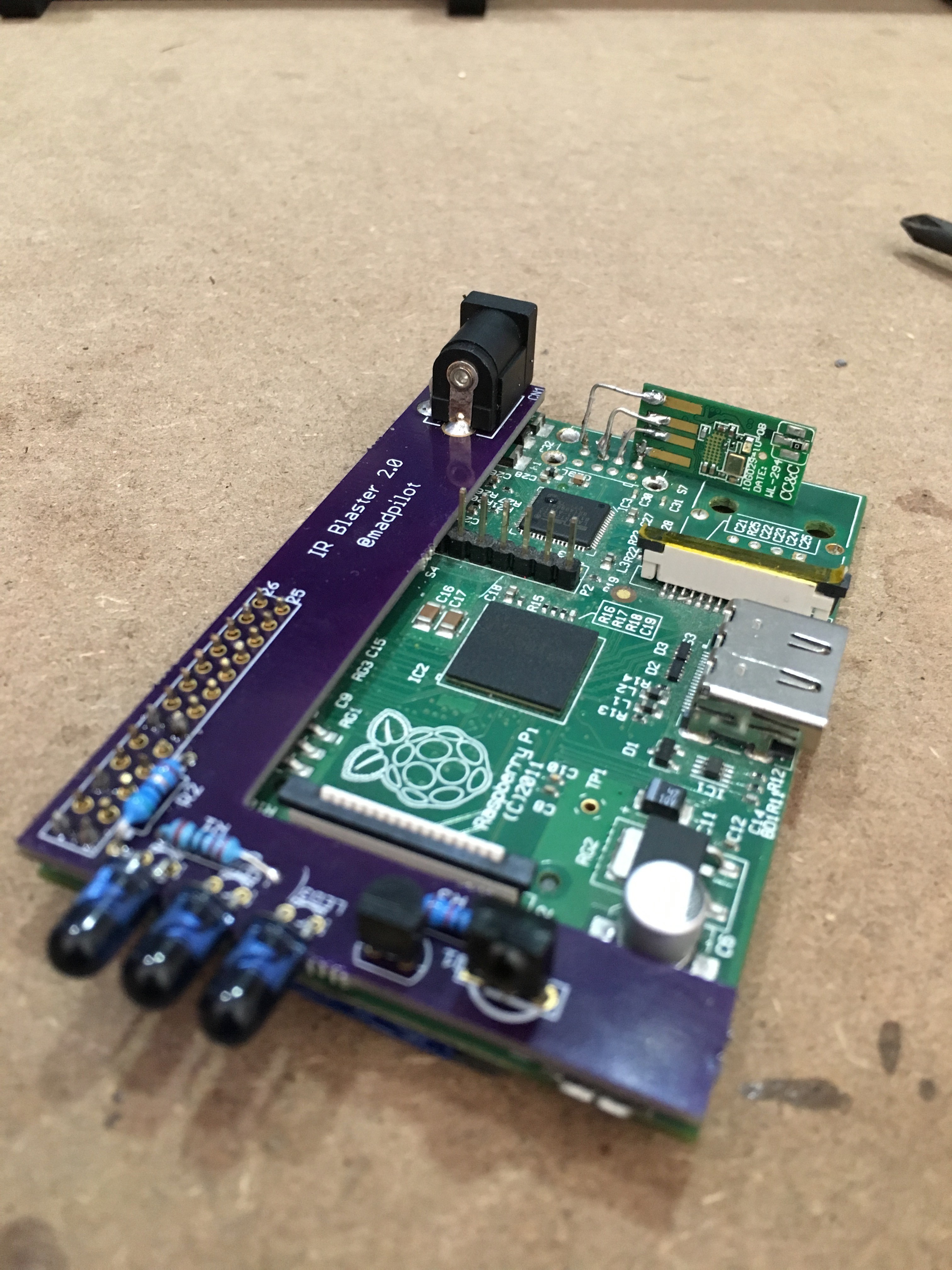
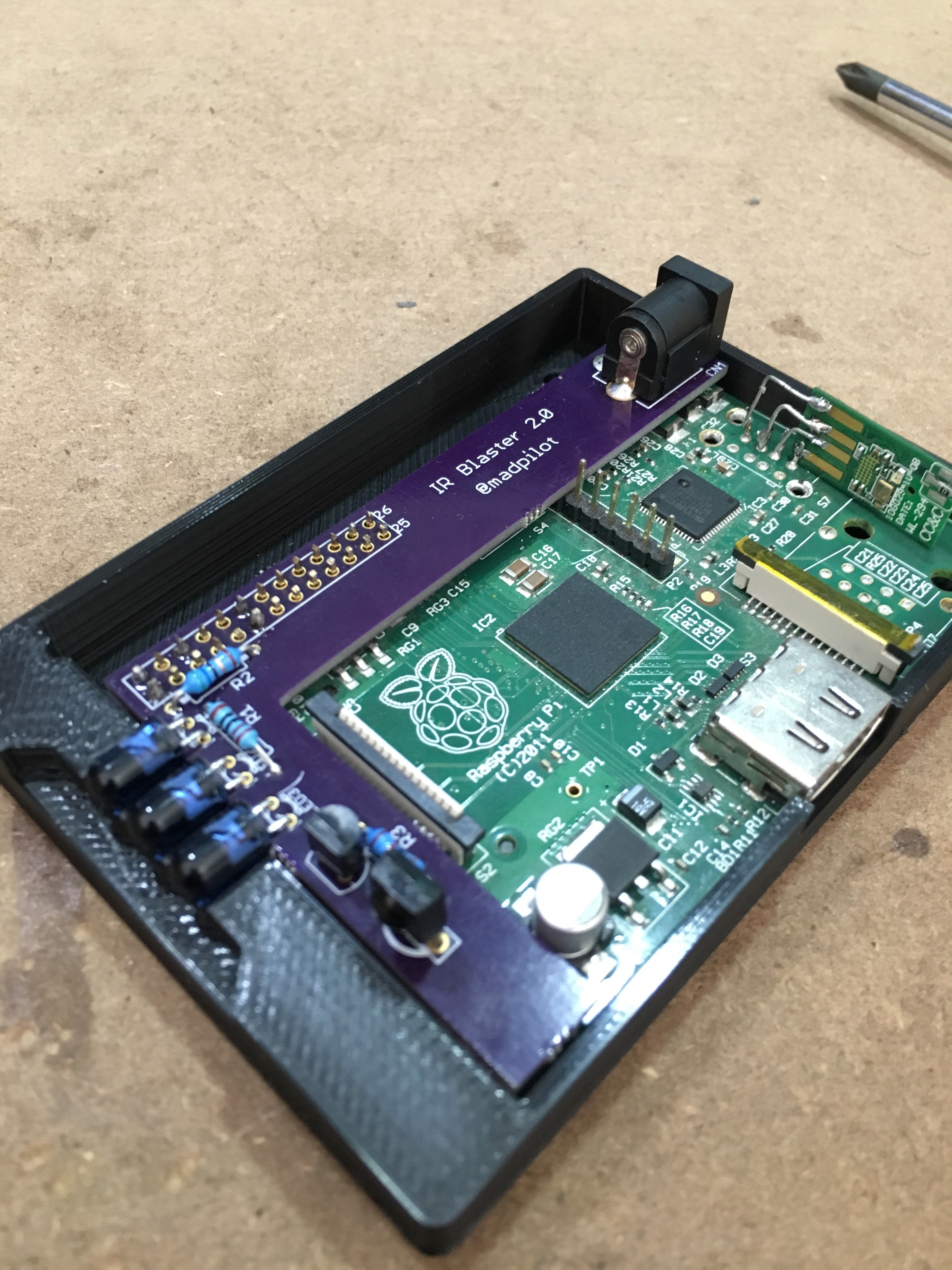
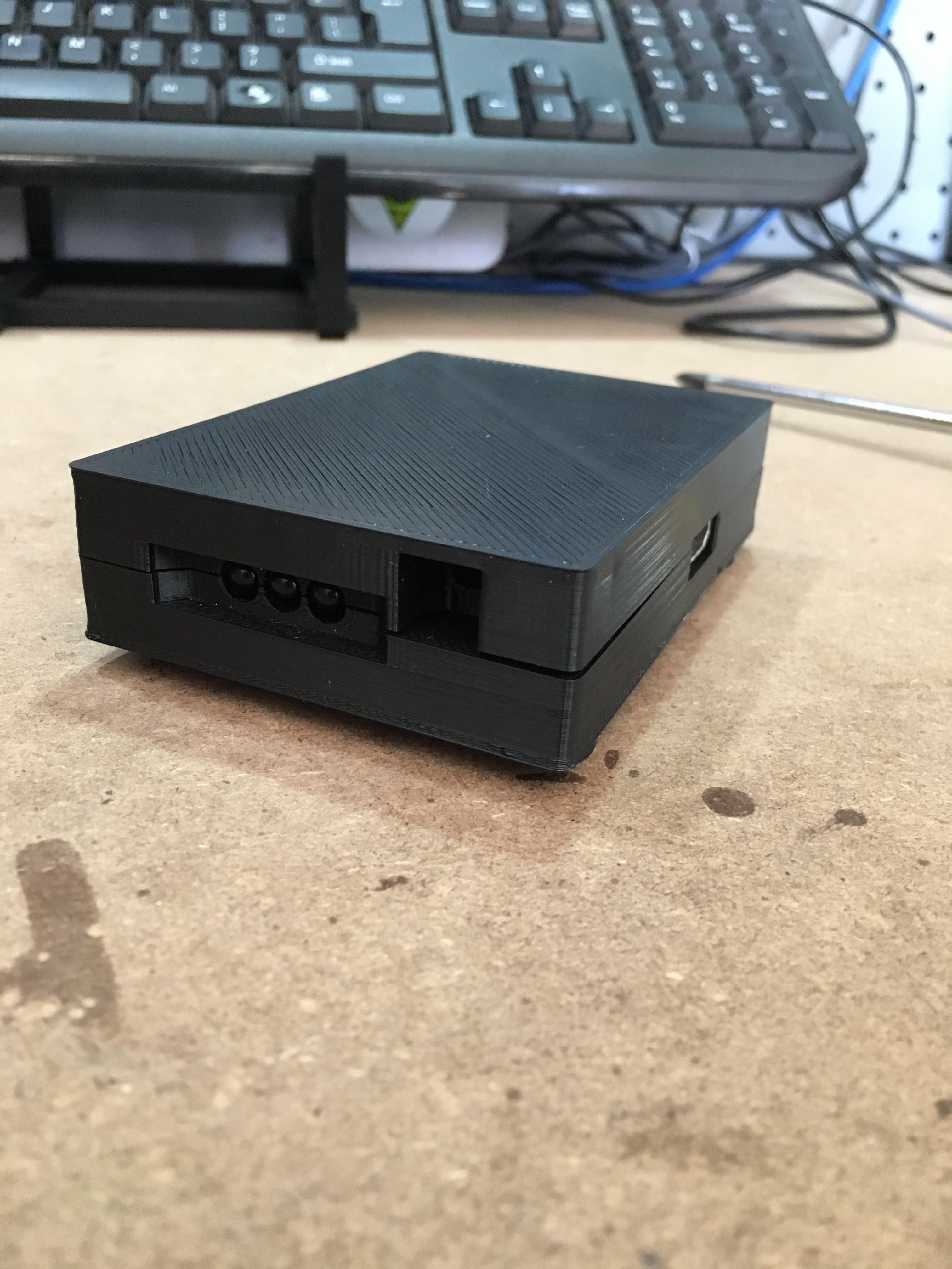
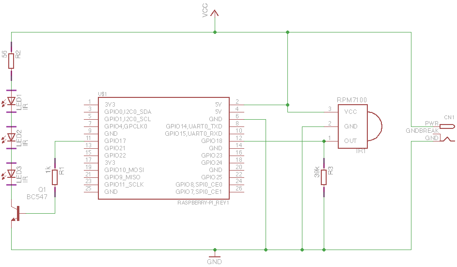
I am not the first person to build an IR blaster for a RaspberryPI, and I sure won’t be the last. Thanks to the LIRC gpio module, the circuit required is super simple:

One side is the transmitter – 3 IR LEDs in series, with a 56ohm resistor, driven by a bog-standard BC547 transistor.

The LEDs I used have a 1.2V at 20mA. forward voltage, so the three in series drop 3.6V. R2 needs to drop 1.4V (to add up to 5V). R = V/I, so R2 needs 70 ohm. For some reason, I picked a 56 ohm resistors, so the LEDs will get driven a little harder at 25mA, which is still well with in their spec (They max out at 50mA).

The transmitter side is even easier – the device does all the work, so there is just a pull down resistor on the signal leg. I picked GPIO 17 and 18 at random – any GPIO line will work, and you can configure it in software.

IR-blaster with CEC – CEC *throws hands in the air*

CEC is actually a very simple protocol. Each packet is at least two bytes, the first nibble: an integer between 0 and 16 representing the sender, the second an integer between 0 and 16 representing the receiver, followed by a byte-long opcode. Some opcodes allow additional parameters.

All devices talk in “party line” mode, meaning everyone hears every message (there is a maximum of 16 devices, so routing and partitioning is overkill). It also means every device knows what is going on all the time.

The protocol allows you to find out all sorts of interesting information: is a device turned in? What device is currently active?

You can also ask devices to do stuff: turn up the volume, schedule a recording, or switch inputs.

The problem is: no body seems to implement the spec completely. And many manufacturers don’t do it correctly.

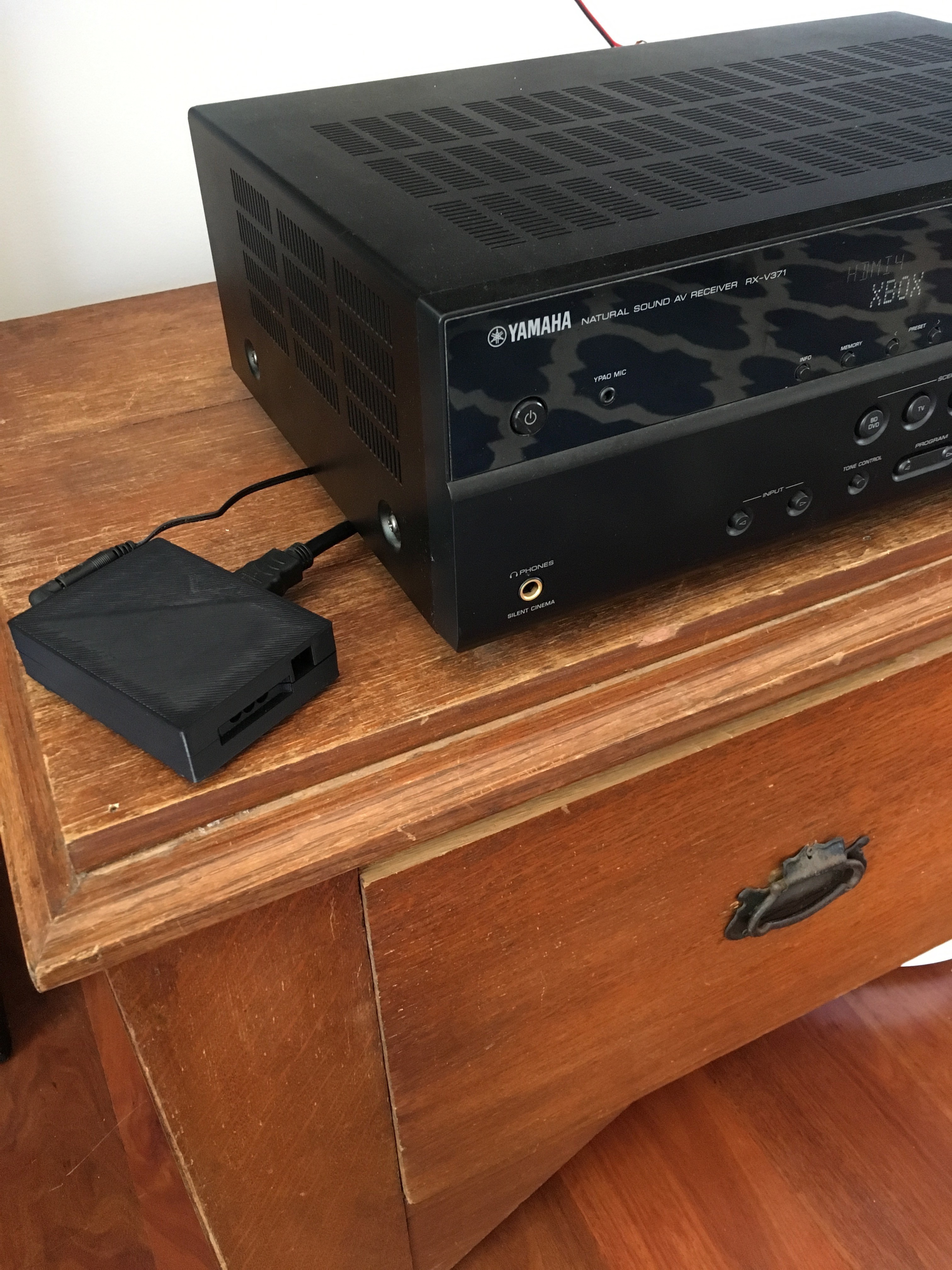
For example: my Yamaha receiver (a RX-V347) supports the user control opcode (0x44) and the change AV input opcode (0x69) which is supposed to take another parameter to denote the input you wish to choose. If the input entered is 0, then the next input is selected. This receiver only accepts 0 as a input code, which makes selecting a specific input (without knowledge of what the current input is) impossible.

There was a fun work around for this though; my RaspberryPI is connected to a HDMI input in my receiver, which I know the number of. By working out the distance each input number is from that input, I can select the RaspberryPi as the active input then send a change AV input a number of times until the right one is selected. Do it fast enough and no one would notice.

Why don’t I just interrogate the amp and ask it what input is currently selected? I could, but there is only facilities to find out what HDMI input is active. If the AV1 input is active (which has my Sonos attached) I’m out of luck.

Of course, none of this stuff is documented any where so there is a lot of trial and error going on to work out what opcodes each device handles, and whether they handle it correctly.

IR-blaster with CEC – Stripping a Raspberry PI

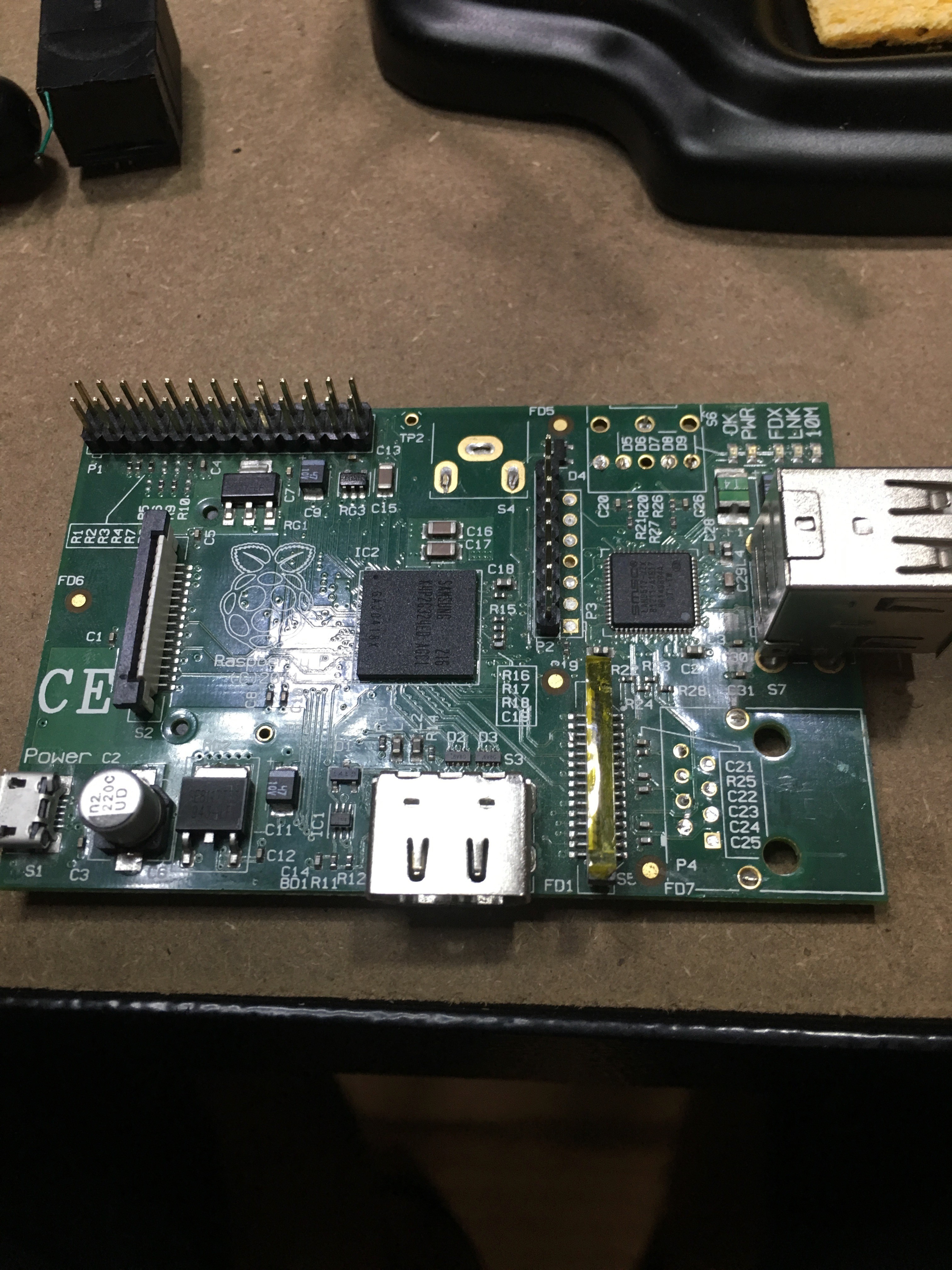
I had a couple of the original Raspberry PIs on my desk, and since they were just sitting gathering dust they seemed like the perfect candidate for this project.

I don’t know why, by the composite port really irks me. I’m never going to use it, and it really juts out, and realistically this was going to be WiFi only, so I could get rid of the network port. Also, plugging in a Wifi adapter made the board unnecessarily long.

Time to trim it down a bit.

First, I removed the composite port by clipping the leads and desoldering the remains.

Then I removed the network plug. The two holes that held it in will come in handy later…

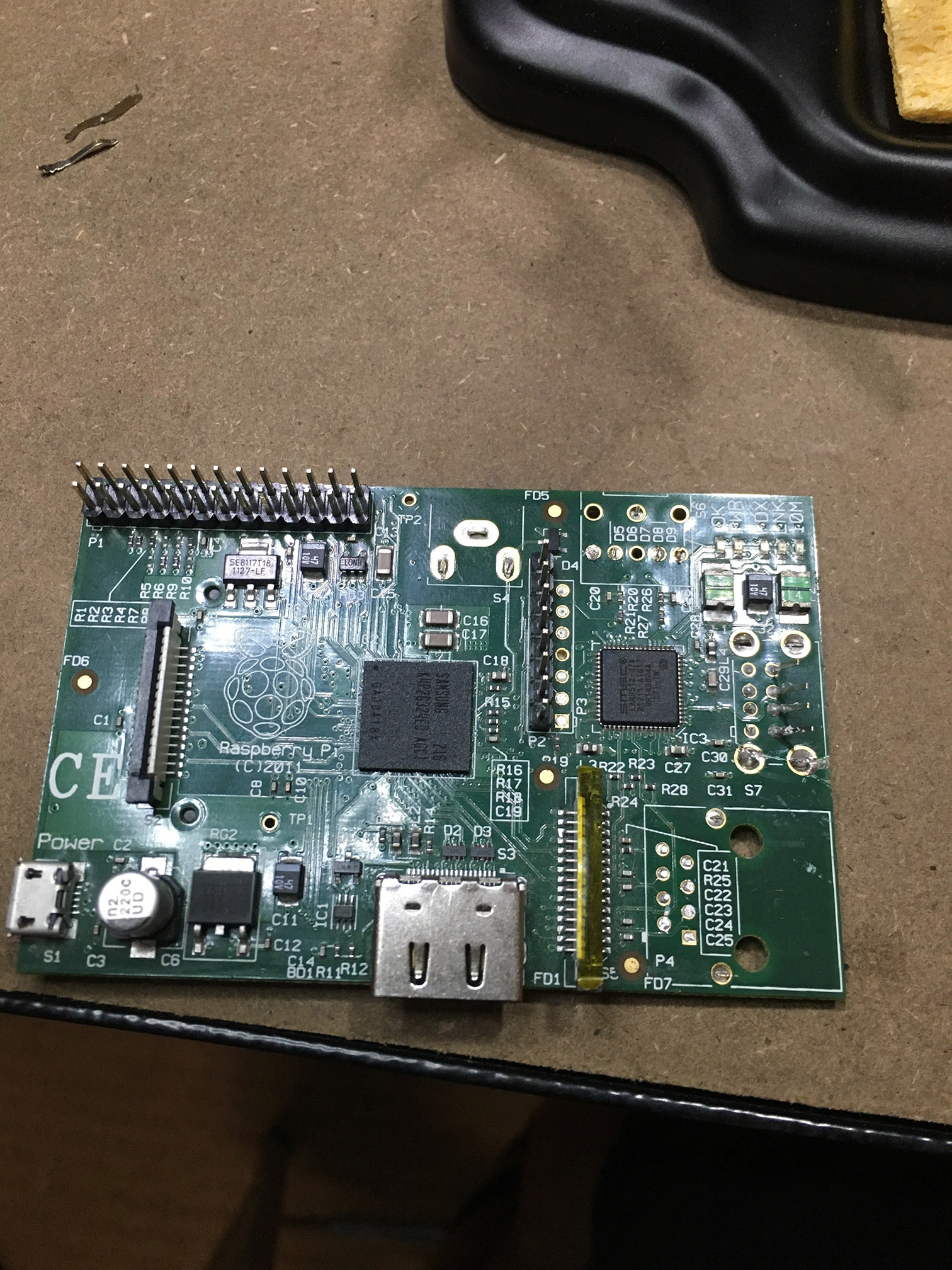
Finally, I removed the USB sockets.

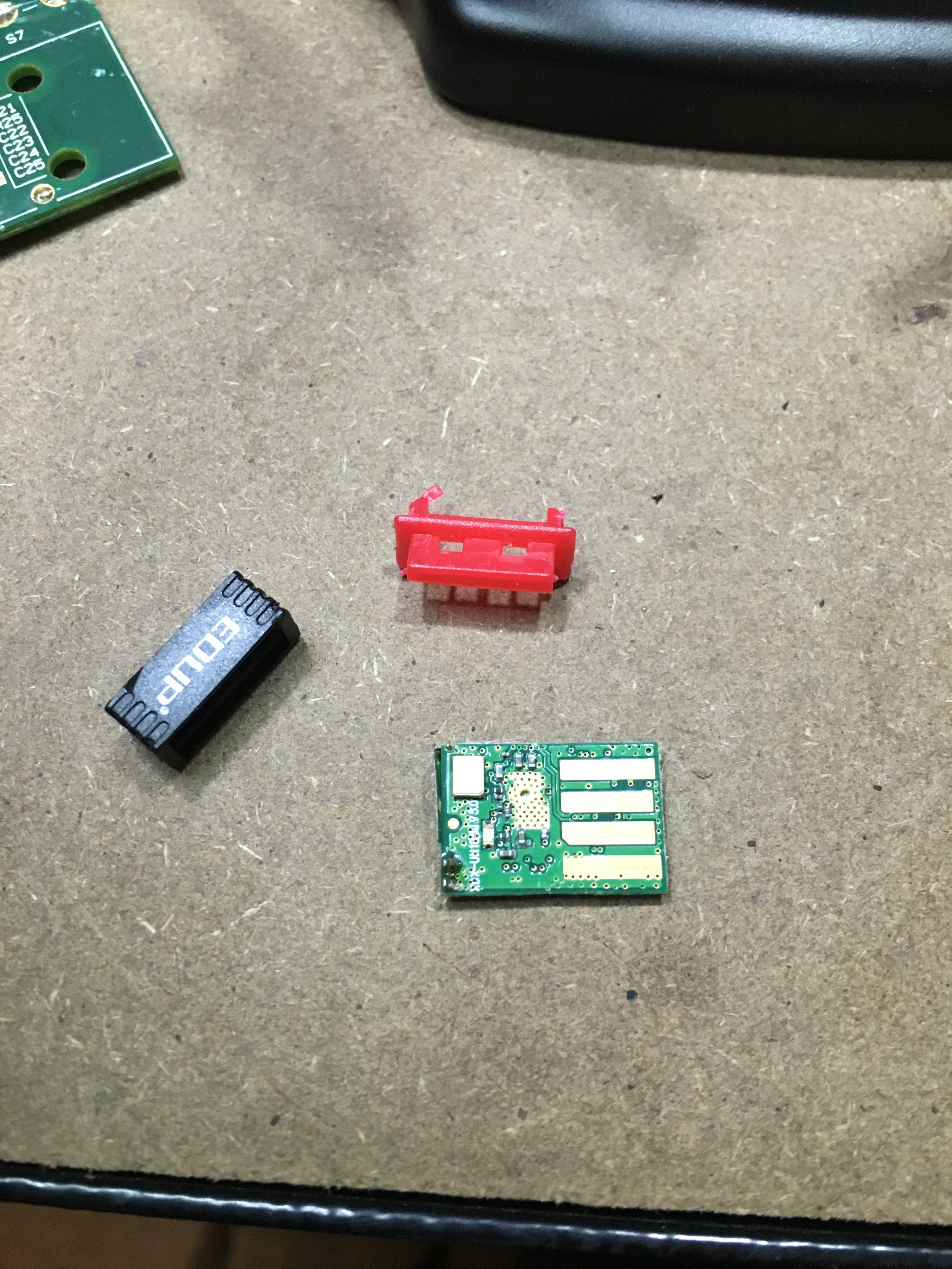
Much neater! And regular shaped. Of course, there is now no way to interface with it. I took a perfectly good USB WiFi module and gutted that.

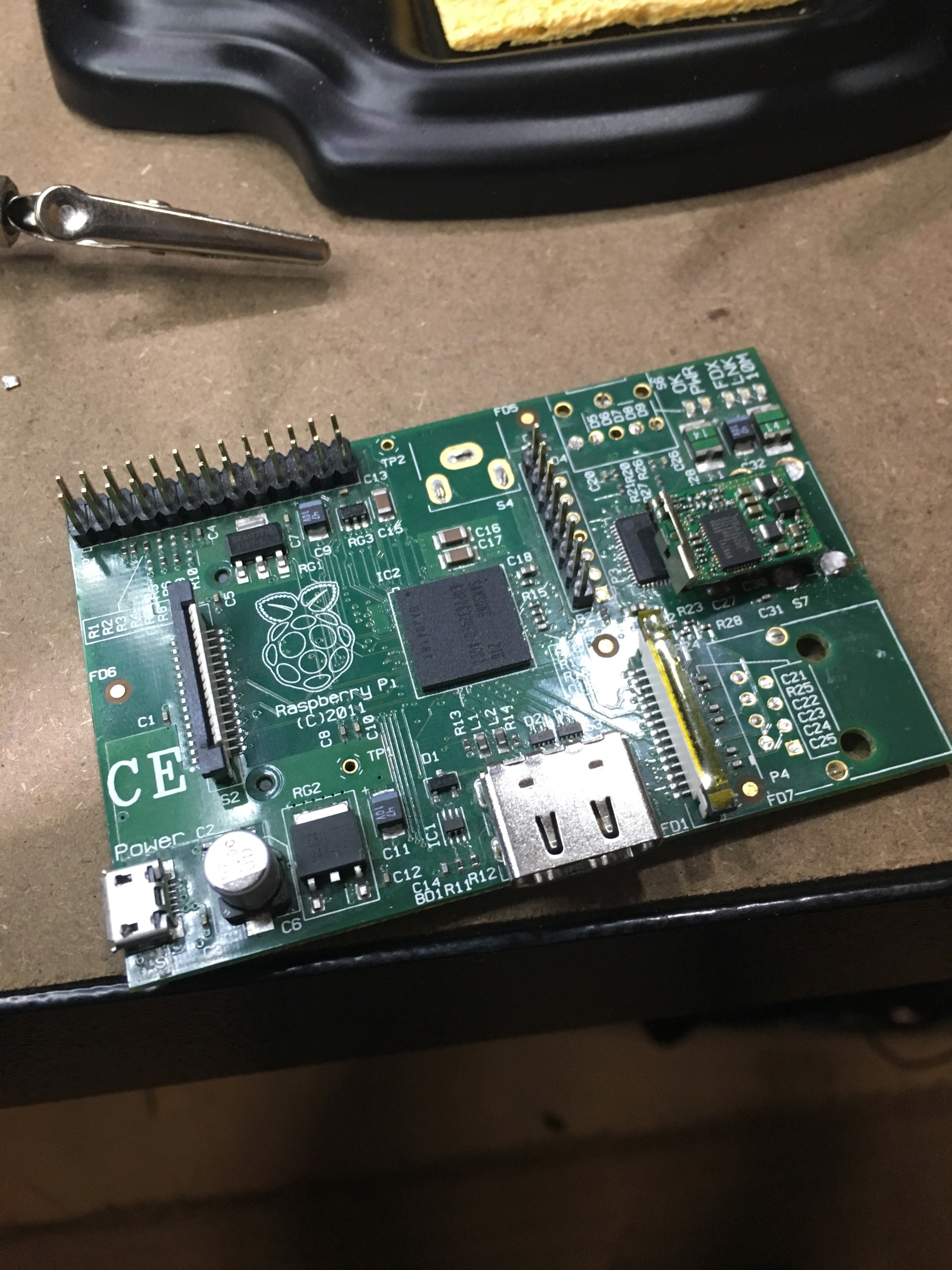
And then direct soldered it to the PI.

Now I have a minimalist WiFi-enabled RaspberryPI! If I need to make any changes, I just ssh in and do it via command line. If I really need a keyboard, I’ll just put the SD card in another PI that is more fully featured, and do it there.

Next up: the IR blaster board

IR-blaster with CEC – Project (log) kick off

Full disclosure: I started this project a while ago – according to the photo app on my phone, almost 12 months ago! I originally wanted to build it so I could control my TV, Yamaha receiver, Foxtel set-top box and Apple TV from my phone and watch. I like to listen to music while I cook, but changing the song, or the volume is a pain – I have to stop, wash and dry my hands, then walk over to find the remote.

The project got shelved for a while (Oooh! shiny things!), as I worked on my garage door project, but then I had an excuse to resurrect it.

My wife casually mentioned that she wanted to be able to stream music, and listen to the radio at the back of the house. And even in the front room, she found turning on the Apple TV to stream Spotify annoying. She also hated having to turn on the TV just to play.

There was only one solution I could see: Purchase a Sonos!

I actually purchased two: A Sonos Play:1, that we can move around the house as we need it – it usually lives in the bedroom, but we can easily take it outside when we have people over; and a Sonos CONNECT – I already have a perfectly good receiver and speaker setup, replacing all of it sounded like over kill.

Now we could stream music around the house easily without it stopping if the phone rang, and without draining our phone batteries. There was still a small issue though: the Play:1 turns on as soon as your press play on the phone app, as does the CONNECT. Unfortunately, my receiver didn’t.

Time to dust off the IR blaster.

The CONNECT publishes uPNP data, which homeassistant.io already listens to. This in turn fires an event when ever the devices starts playing music, which I consume using node-red, which makes an API call to another node app I have running on a Raspberry PI, which in turn blasts out some IR via LIRC.

Simple really :)

I’ll write up the different parts over the next couple of weeks.

Garage Door Opener – Yeah. So it works

Garage Door Opener – Hardware test

Even though I still have to complete the captivate portal, and over-the-air updates, It seemed like a good time to wire the controller in and see how it all works off the bench.

It’s a good thing I did, as I discovered a few issues with the board.

Excuse the wiring, it’s just temporary…

Originally, I had two switches: one of when the door was completely open, and one for completely closed. Based on the last state, I could guess whether the door was opening or closing. I must admit, I realised long after I ordered and built the board that I really only needed one switch that indicated the closed position. Good thing really, because the device got completely confused after I installed it.

Back story

Because of the limited number of IO pins on the ESP8266-01, I had to pull some tricks to give me two switches and a relay (I can’t take credit, this is an amalgam of a bunch of stuff I found Googling).

There are 4 GPIOs, two of which are shared with the TX and RX pins on the serial port. To make things even more interesting, GPIO0 needs to be held high on boot, otherwise the device goes in to programming mode.

This means GPIO0 is no good as a switch interface – if there was a power outage and the switch attached to GPIO0 was closed as it rebooted, the device would be stuck in program mode.

Conversely, when the device boots up, there is a bit of chatter on TX, so putting the relay on that would be risky – a reboot could cause the door to trigger, and open it when no one was home.

Wiring the relay to GPIO0 and GPIO2 is quite easy, pull them high with pull-up resistors, then switch them to outputs during the setup phase. Setting them both low at the same time sets the relay up. Pulling GPIO2 up, drives the base of a transistor and energises the relay. While the output of the chip could drive the relay directly, I’m actually using a 12v relay that is driven from the convenient 12V output from the garage door controller, so the transistor is required to switch the higher voltage from the lower 3.3V coming out of the regulator.

The “closed” switch is wired to the RX pin, and the “open” switch is wired to the TX pin. This means that the Serial Port is disabled, which can make debugging difficult, so as I work, I usually disable the switches.

This all worked fine on my bench, but as soon as I installed it the close switch wouldn’t register properly, and I couldn’t work out for the life of me why. I suspect the internal state machine wasn’t transitioning properly, possibly because of contact bounce, but it turns out it didn’t matter – I also found what I would call a show stopper: I discovered that if the TX pin was held high (ie the device booted when the door was open) it would never start.

Not ideal.

In a quick refactor of the code, I disabled the state machine, replacing it with a simpler open/close state – if the “closed” switch is closed, the device reports closed, if it’s open, it reports open. Keep it Simple. Who knew, right? Another nice side effect is I can use Serial.println for debugging again. Bonus.

So that brings the mistake count for that board up to four – thankfully all workaroundable (totally a word)fairly easily:

  1. “Open” switch not needed
  2. TX and RX pins on the FTDI connector are transposed (fixed by modifying my FTDI cable, which I’m sure will come back to bite me at some point)
  3. Originally, the GND for both switches shared a screw terminal, although now I can get rid of the open switch, I can keep the board to five screw terminals.
  4. No room for the heatsink
  5. (Improvement) Add a jumper to switch between using the 5V off the FTDI cable and an external supply – I was using a fly leads soldered to the bottom of the board while testing.

As a PCB board designer, I’m an excellent software engineer.

Garage Door Opener – Storing the configuration II

I wrote about my “generic” config class in a previous build log, and alluded to how I wasn’t really sure it was the best plan of attack.

It wasn’t.

All of the casting was painful, the setup was annoying and unnecessary (From both a memory and CPU time POV) – there was little (if any) advantage in using it.

In the end, I wrote a concrete class with mutators for each attribute. This meant each attribute is already the correct type, so there was no annoying casting, and I could control and optimise the serialisation and deserialisation.

You can see the class on Github.

The mutators are pretty straight forward, as is the serialisation:

The boolean values (as well as encryption mode and mqtt Auth mode) are compacted using bit-masks, effectively fitting five config items into one byte. Next, I store single integer and double integer values (I use doubles for port numbers), and finally strings.

The strings are encoded by putting their length in the first byte, effectively limiting string length to 255 characters, which is fine – DNS names are limited to this, and that is the biggest thing the config will store. It also makes it possible to avoid overruns, as we have an effective upper limit, so if we go past that index, we know something is broken.

Previous Next