@madpilot makes

Turning a Makibox into a PCB Mill

You might remember the Makibox A6 – it was a sub-$400 3D printer that, like a lot of cheap printers at the time, was crowd-funded. It took forever to deliver, and there were a lot of problems with it.

The MakiBox A6LT

Personally, I managed to print a single cube on my first print. On my second print something went wrong and I blew up the control board. I suspect because of the stalled extruder motor. The extruder needed replacing, as did one of the plastic lead screws (that was my fault – I over tightened it).

In the process of trying to get the parts replaced, the delivery got lost – they claimed it had been delivered, but I hadn’t received yet. While trying to work this out, I had to quickly move interstate for work. To make matters worse, the company that made the Makibox disappeared around the same time, so I resolved myself to writing off the printer.

I decided to move to Melbourne permanently, so I flew back to Perth to collect my belongings – included what was left of the Makibox – and jammed it into my car for long drive over the Nullarbor.

And there is sat almost four years – dejected, in a cardboard box in my workshop.

On a recent trip back to Perth, my mother handed me a package which a person I worked with have given her. Apparently. it was delivered to the office years ago – so I had no idea what it was.

Low and behold, It was the replacement parts from my Makibox! Well, this was a sign. I put the parts next to the printer, as I wasn’t sure what I was going to do with it. I had an M3D printer which was pretty terrible – maybe I could frankenstein the two designs and get one printer out of them?

Fast forward a couple of months – I come in to a bit of spare cash after selling off my time tracking application, and I decide to bite the bullet and buy a real 3D printer – a Lulzbot Mini. After setting it up and kicking out a number of awesome prints, I placed the M3D next to the Makibox. I now had a collection of old, cheap and not very good printers. I had to do something about that.

Upcycling a Makibox

The Makibox has some decent steppers and screws in it (the M3D really doesn’t – half the problem really) so I started looking at the parts and wondering if I could convert it to a PCB mill. Ideally I’ll eventually want a proper mill that can do aluminium and stuff, but I reckon I can cobbled together something good enough to grind a few hundred micros of copper off some fibre glass. Bonus points if it’ll drill through holes.

What’s the worst that can happen? I have a broken Makibox?

Research

I’ve been doing some research into PCB mill designs over the past couple of weeks, and I’ve decided to go with a fixed gantry design (based heavily off the cheap Chinese machines). This means I only need three motors, and three lead screws.

I’m giving myself a $250 budget for the conversion.

Due to the existing hardware that I want to reuse, the actual build area for this machine will be relatively small, so I’m hoping that will help with the rigidity of the system (smaller builds should be stronger than larger ones). Given that this PCB mill gets decent results with a wood base, I’m feeling pretty confident we can get some good results with this.

Stocktake

  • 4 x NEMA 17 sized motors (Longs: 17HS 42BYGH 1.8°)
  • 1 x 218mm T8.8 (8mm diameter, 8mm travel per revolution) trapezoidal lead-screw
  • 1 x 165mm T8.8 trapezoidal lead-screw
  • 1 x 147mm T8.8 trapezoidal lead-screw
  • 2 x 226mm x 4mm steel rod
  • 1 x 170mm x 4mm steel rod
  • 1 x 164mm x 4mm steel rod
  • A bunch of cap hex screws
  • Plastic couplers
  • Plastic anti-backlash nuts

The plastic anti-backlash nuts are surprisingly good – I can’t detect any backlash (with the naked eye). The injected plastic piece has some thread that acts as a preloader – quite clever really. Regardless, I decided to order some metal anti-backlash nuts – I’m not sure how the plastic will hold up to the additional force of milling.

I also ordered some aluminium couplers (to replace the plastic ones), LM4UU linear bearings (to slide on the steel rods), and round bearings to hold the lead screws. Total cost so far: $79.68.

Everything else looks useable (at this stage) – I’m a bit concerned that the steel rods aren’t straight enough, but I’ll run with them for the moment.

I’m going with 4040 aluminium t-slot for the frame. I’ve found a Melbourne based supplier so I should be able to get high-quality stock quickly (and cut to size!). But before I order them, I’m going to design the mill in Fusion 360 so I can test for fit and size.

You can see the render of the Y-axis here:

Render of the Y-Axis

The X-axis will be a (wider) copy, rotated 90 degrees. The Z-axis will still need some thinking.

I will print the motor bracket, bed and bearing holder on my Lulzbot Mini. This is is the cause of the weird design – it needs to fit in the 150mm x 150mm build envelope of the 3D printer.

Based on the dimensions from Fusion 360 the design should allow a Y-axis travel of around 168mm 156mm (Update: I didn’t take in to account the linear bearing width). I still have to work out the X-axis travel.

Hugo’s Nightlight: Part I

Long before Hugo was born, I had hatched a plan to build him a nightlight. Originally inspired by this, I decided to go for something less fragile – a simple H with some RGB LEDs.

Just before Hugo was born, I added a LIFX bulb to our bed side table, and added some Flic buttons that gave us better control on the lights. Using a Node Red flow, I setup the light to go to 5% brightness on a single click, 20% on a double click and a 2 second hold set the light to 100%. This worked really well: if we wanted to check on the baby, we could just single click, and get enough light to see him without waking him.

The downside was if the Flics stopped working we needed to use our phones, so the second requirement was a hardware switch to turn the light on and off. It should have configurable single, double and hold actions.

After Hugo moved to his own room, I wired up the same LIFX and Flic setup, adding a slow fade to the lights, so as to not startle the little fella when the lights switched on or off. I wanted the night light to do the same, so it would need some sort of tweening library.

Finally, a mate of mine was telling me about his kids grow light that turns on in the morning to let the child know that it’s time to wake up. I thought it would be kind of fun to have a cute sun rising animation. I thought about adding an alarm feature in to the light, but decided that I can do that using home assistant and node red, which saved me adding a Real-time clock and having to deal with times and other such nonsense.

Giving these requirements I went and ordered a tape of WS2812B LEDS from AliExpress ($12 for 100!) and got to work.

Making a plastic H

I needed a translucent H. My first thought was to try the usual places to see if there was something I could buy off the shelf. There was a few places that sold acrylic signs that would have been suitable, but they weren’t quite what I was looking for. I really wanted a completely milky white H with the LEDs embedded in the middle.

Well, I have a 3D printed, could I do something with that? I went in a hunt for translucent white filament. It turns out (for reasons I will discover later) that isn’t a thing. Odd.

I picked up some light blue translucent filament and did a small test print, but the print came out really streaky. Not what I wanted.

Then I remembered reading about resin casting. What if I could print a master, cast a mold in silicon, then cast the whole thing in resin? A quick Google for some tutorials and it sees plausible – in fact a bunch of people embed LEDs for cos play jewellery.

The problem is, all the examples I see are clear. You can get pigments to embed in the resin, but a white translucent one alludes me. Hmmm.

At this point I decided to go in to the local Barnes (a store that specialised in casting and other craft stuff) and had a chat with the staff. Apparently white translucent is really hard. The lady I spoke to thought that I might be able to get the effect I want by using a really small amount of pigment. Like, really small (she says that fully opaque happens at about 2%).

I buy a starter pack which has the 500mL of pink silicon, 500mL of resin and a bunch of measuring cups, containers and stirrers. I also bought some modelling clay and some spray on wax as I needed to make a two part mold. Unfortunately, this stuff ain’t cheap – all up it cost me $150.

Next step: Make the master.

Installing IKEA Filur bins into a kitchen cupboard without drilling holes!

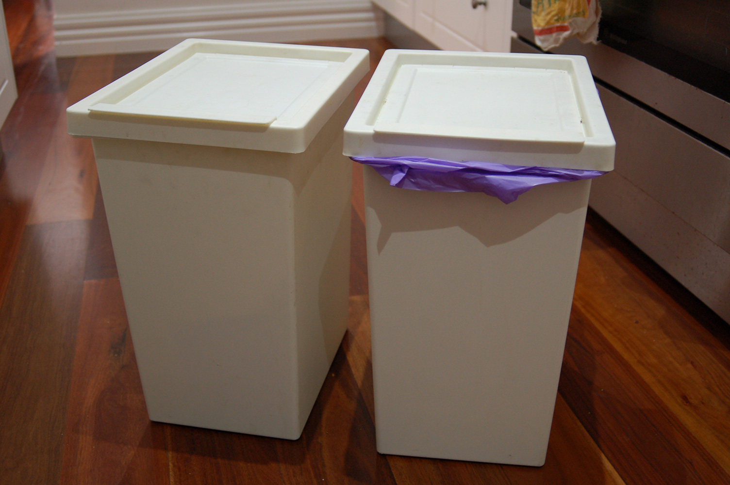
We have two IKEA FILUR bins that we use in our kitchen – one for waste and one for recycling. To stay out of the way, they live in the butler’s pantry. This is a little bit inconvenient though – moving scraps around inevitably means dirty floors.

The IKEA FILUR bins

My wife decided to do a spring clean, and managed to free up a cupboard with the intention of installing cupboard bins. Easy enough. We started looking around, and found them quite small – we’d become accustomed to the good size bins that we already had. Not only that, but new units seemed quite expensive. We weren’t going to spend a lot of money and end up with something worse.

So I decided to build some.

The cupboard have shelf support holes, as most modern kitchens do, so I set myself a constraint: No drilling holes into the existing cupboards. This would allow us to restore the shelves if the bin-in-a-cupboard thing didn’t work, or we decided to move them to another cupboard, or we decided to move house, or some other reason that forced us to remove them.

The first step was the make sure the bins would both physically fit in the cupboard – and they did. By placing them sideways (Which actually made a lot of sense in this case) they fit with just enough space around them. This also allowed us to test a MVP – would having the bins in the cupboard work for us? After a week, we didn’t hate it, so on to the next step.

Time to jump in to Fusion 360, and have a bit of a play around with a few ideas and some dimensions.

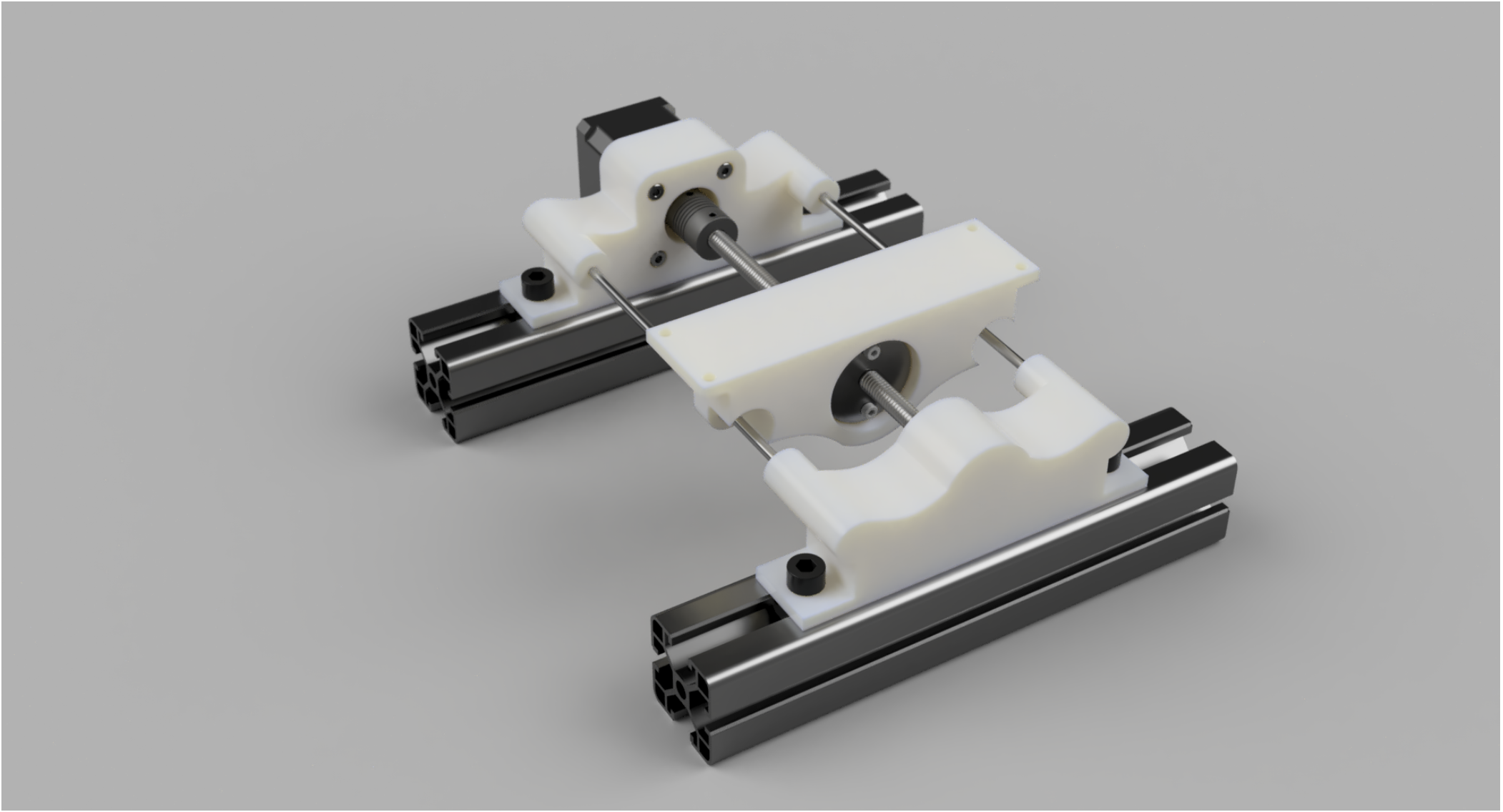
My first thought was to have attach some drawer runners to two rectangles of wood that ran around the inside of the cupboard, but this seemed overkill, and the dimensions were a little too tight to make it really work. Next, I wondered about 3D printing some brackets that would hold the drawer runners. I jumped on to the Bunnings web site to find some drawer runners, and I found some likely candidates for just $11. The problem was (as always) no accurate design drawings or dimensions.

But for $11 (and Bunnings’ generous returns policy), I was willing to take a punt.

The Drawer runners attached to the shelf

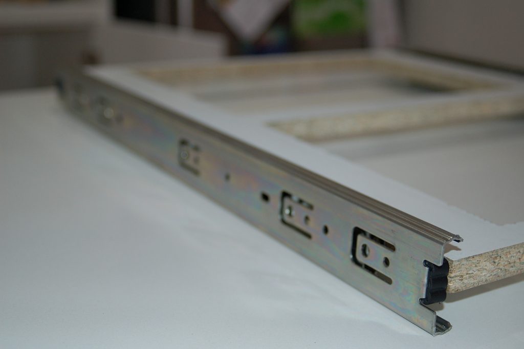
The next problem was how to attach the brackets to the walls of the cupboard. 3D printed plastic nubs probably wasn’t going to cut it – I could see them snapping off in the holes. Next, I thought about embedding some 5mm metal rod, or perhaps removing the plastic off the existing shelf supports. I then did a quick search on the Bunnings website and found these all metal shelf supports with metal lugs that would work perfectly (for a grand total off $2.67!). Off to Bunnings!

One sausage sizzle later, I had the bits I needed.

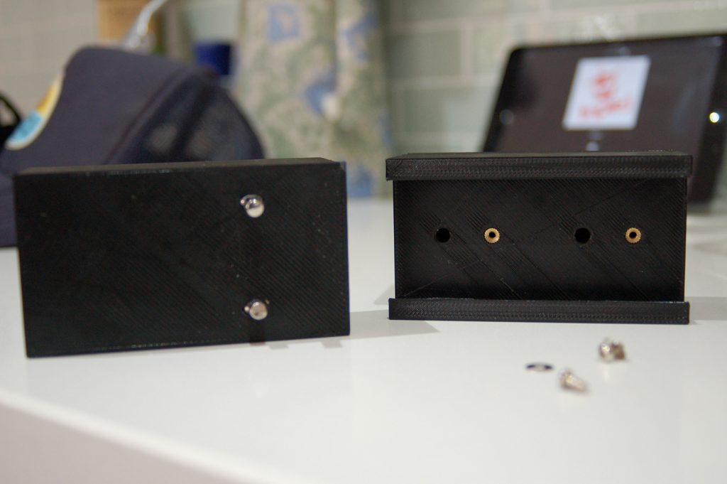
Now I had the dimensions of the drawer runners and the supports, I whipped up a quick design, and 2 hours later I had printed the first bracket to test for fit. Initially, I was going to rely on brass inserts and screws to secure the runners, but I added a small curve to add a some additional support. This worked out better than expected – the curves would happily hold the runners without the screws (although I still added two screws on the back off the runners to keep them in place when pulling out the bins). When it came to attaching the metal inserts, I thought of using heat like I did with the brass inserts, but it turned out a hammer and friction was enough to hold them in – and the platform that the bins would live in would actually push the runners out, holding the whole thing together.

So over the next 6 hours, I printed the remainder of the brackets.

Two of the printed bracket

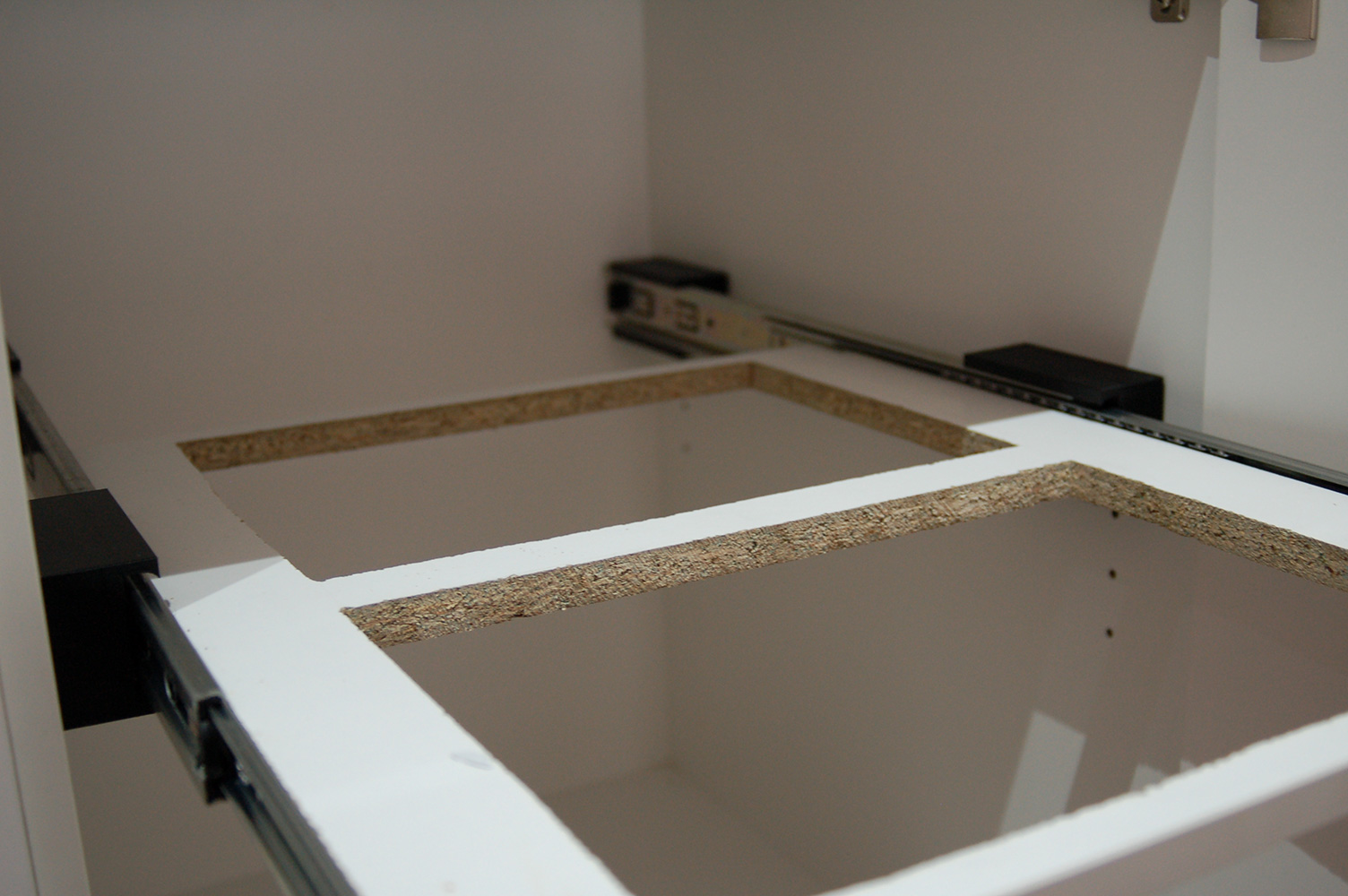
Once the were done and installed, I could get final measurements for the shelf. This was where designing it in CAD helped – according to my calculations, it would need to be 420mm, and I was dead on. Initially, I was going to buy some melamine coated MDF, but then I decide to cut the existing shelf (which just so happened to be melamine coated MDF) to size.

Cutting the 500x550mm panel to 420x550mm was easy work, but the internal holes for the bins were a little more challenging as I couldn’t find my jigsaw. I used a multisaw, which in theory should be the same, but was ended up being slower and more difficult to use. As a result, the holes looked like it was cutout by a drunk monkey. Nothing a bit of rasping couldn’t fix. Besides – the bins will cover a multitude of sins. All in all, the result was good enough.

Fitted

It was at this point, I made a minor mistake in drilling the holes for the runners – they are offset from centre, and I drilled one side on the wrong side, but that was easy enough to fix, just by drilling them on the other side of the centre line.

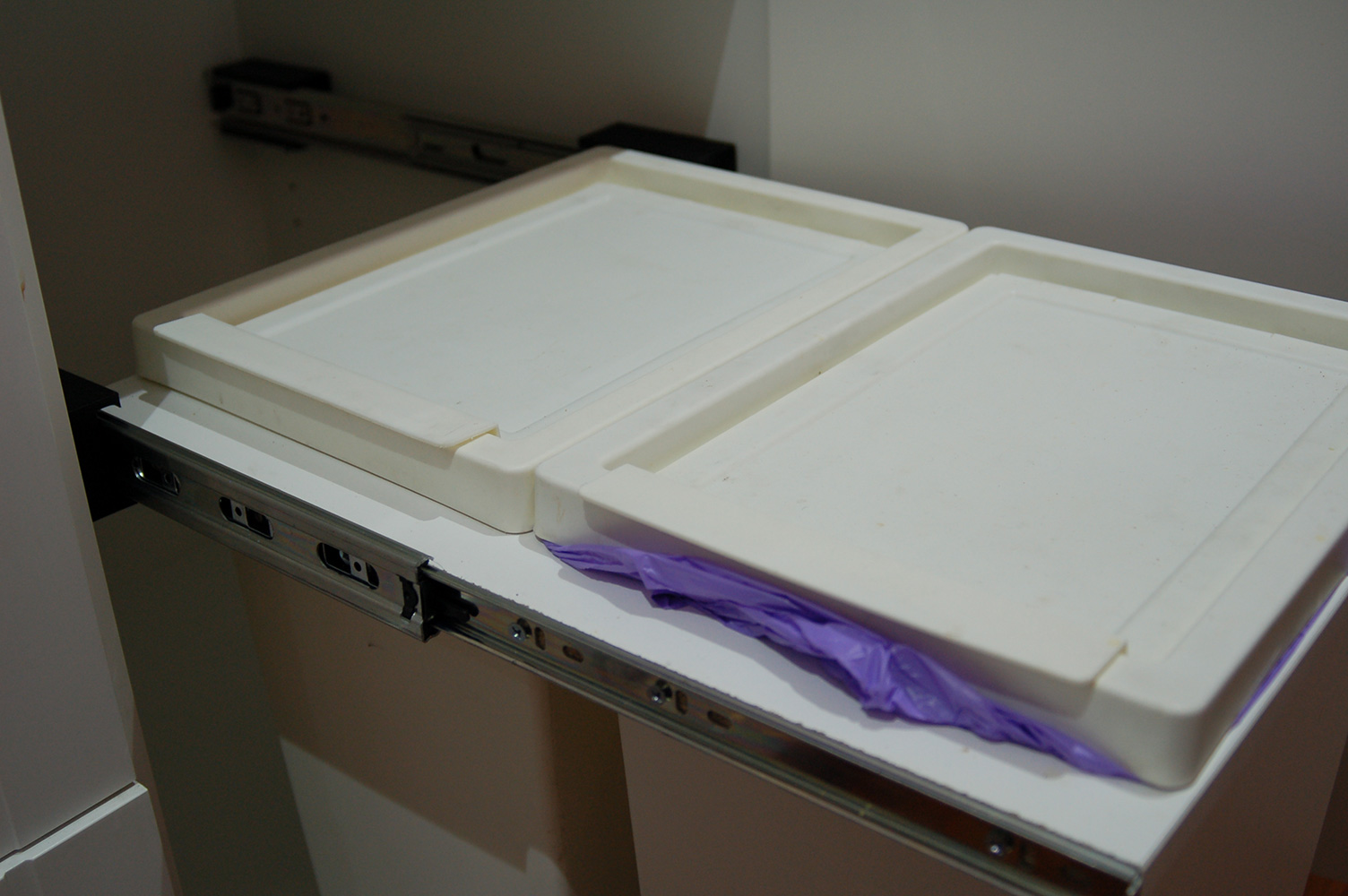
Putting it together was slightly more challenging, as I needed to screw in the support screws whilst in-situ, and had to do a bit of a contortion act to get them in. But once it was in, it all worked really well. The shelf could have possibly done with 1mm extra cutout, so the run was a little smoother, but it’s totally fine as is.

The bins installed on the drawer

The other thing I would change it to make the non-door side thinner, so the there wasn’t such a massive gap between the cupboard wall and the runner – the gap on he door side is needed to give clearance from the hinges, and I went for symmetry, but it does look a little odd. It would have made the print time much less too. Oh well – next time!

So for a grand total of $13.67 (plus about $3 in plastic), 45 minutes off design time, and 8 hours of print time, our bins now live in a cupboard!

Download the design on Thingiverse.

A case and POE for the OrangePI

Technically, the OrangePI Zero supports a type of Power of Ethernet, but this makes it compliant.

..and uses a cheat – you can buy POE splitters off Aliexpress – this hack removes the Ethernet port off the OrangePI, and permanently attaches the splitter. I also 3D printed a case for it, which is the interesting part, as I experiment with post production.

I use an OrangePi as a server for my Flic bluetooth buttons. I use POE to power it, so I don’t need to bother with plug packs, however, it all looks a little untidy (why do Pi clone manufacturers always put the power plug on the front!?).

I’ve also been meaning to experiment with sanding and spray painting 3D prints, so I thought I’d kill two birds with one stone.

Adding the POE splitter to the OrangePi

  1. Desolder the Ethernet socket from the OrangePI. I used a desoldering needle.
  2. Desolder the ethernet and power cable from the POE splitter
  3. Use ethernet cable to join to the two Ethernet pads. Make sure you maintain the twists between pairs. I also soldered two pin headers into the support holes either side of the Ethernet sockets, to give some physical support.

Printing the Case

  1. You can download the models from Thingiverse
  2. No need for to print supports – 20% infill is fine. Once printed, you need to cut off the board support clips at the top of the pylons – they don’t work. Drill two 2.5mm holes in the two rear pylons.
  3. Insert brass inserts into the corner holes.

Painting

FDM 3D printing is quite streaky, and looks… well, like it was 3D printed. I print in PLA, so acetate vapor is out off the question, making good, old fashioned sanding and painting the easiest way to get it looking it good.

The first time I tried this I sanded the thing completely smooth, and it took ages. I found other people have had success using automotive primer/filler which fills smaller scratches.

I tried this, but the gaps were too big. I went aggressive, and started with 120grit wet-and-dry sand paper. I added another two coats of primer/filler. Next, I went to town with 400 grit, then 800 grit.

I wanted to see if I could paint a logo in the top, so I did an undercoat of satin silver, placed a sticker over it and then painted a top coat of satin grey.

It looked terrible.

  1. The sticker lifted, so the edges off the logo were blurry.
  2. Satin shows up ALL the gaps, so even after all the sanding, the lines were still visible
  3. I over painted, so there was drips, and it looked thick and gross
  4. The colour wasn’t… great.

I re-sanded with 400-grit to get rid of the paint, and polished again with 800-grit. This time I omitted the extra coat of primer/filler, and just applied two LIGHT coats of flat (matt) black paint. This time the result was great!

Matt paint actually fills gaps a little bit, so the result is much better. There are still some visible lines (in the right light), so clearly I need to sand more. Also – I missed some bits on the bottom section. Clearly I still need some practice.

I wouldn’t mind trying the satin finish again, with out being so heavy handed on the pain

Hacking a Cheap Wifi Outlet

DISCLAIMER: This project plugs in to the mains, which has dangerous voltages and can kill you. Never plug in the device working on this project – you can re-program using an external 5V supply wired up to the same pads that the red and black wires connect to (CONN1).

I have a Rancilio Silvia coffee machine, that needs time to warm up correctly in the morning – 30 minutes gets everything up to temperature, allowing me to draw excellent coffee shots.

For the past couple of years, I run a simple mechanical timer that turns on at 6am, and goes off at 8am which is fine for the days I go to work, but if I work from home, or it’s the weekend, I’m left with a cold coffee machine unless I turn it to manual mode – which often results in me forgetting to turn it off!

To get around this, I’d been planning on getting a smart switch which would integrate with my Home Assistant setup. I looked at the Belkin Wemo, but it seems a little expensive at $80 a pop.

I thought about designing and building my own one, but the prospect of messing around with mains power didn’t excite me, nor did 3D-printing a case – 3D printing plastic, by definition isn’t very fire resistant.

Browsing at least looked the same for $AU20 delivered. Even if it wasn’t ESP8266, I could probably gut it and insert a custom board, so I ordered one.

It arrived pretty quickly.

I promptly pulled it apart. There was a daughter board that looked suspiciously like a ESP8266 although the footprint wasn’t the same as any reference design I could find.

So, I pulled the little metal shield off, and low-and-behold! An ESP8266! Now that I knew we were in business, I installed the iPhone application that comes with it, to try and work out how it was wired up.

The device

This particular switch has an obnoxious blue LED that is used to indicate power, and network connection (it flashes when not connected). It also has a red LED that is on when the relay is turned on. Finally, there is a button that allows you to turn the relay on and off manually.

Pins

A quick google, and I found the pin out of the ESP8266 chip – now it was just a matter of tracing the wiring back to each LED and the switch. I also needed to find where the TX, RX, Reset and GPIO0 were so I could program it.

Here is what I found:

  • GPIO 4 is the Blue LED
  • GPIO 5 is both the Red LED and the Relay
  • GPIO 13 is the button

I’ve marked the TX, RX, Reset and GPIO0 pins on the above image. By wiring these pins up to a FTDI cable, I was able to reprogram the switch, thus freeing me from the shackles of the crappy iOS app, and allowing my home-assistant.io server to talk to the switch.

Now, thanks to a Home Assistant and a NodeRed flow, the coffee machine will turn on between 6:30am and 1pm everyday UNLESS it detects that I’m not home. Nice!

You can see the code that I use (It’s based heavily on my garage door opener project).

If that code is too complicated, I’ve uploaded some example code that will turn the switch into a simple web server.

  1. Create a new Arduino project
  2. Insert the code
  3. Compile and upload
  4. Point your browser at http://esp8266.local/on to switch on and http://eso8266.local/off to switch off

Garage Door Opener – Modifying the ESP8266 Over-the-Air update code

Now that I have the proof of concept code running, it’s time to modify the built in Arduino core library that handles OTA updates.

The existing OTA library takes a binary object and an optional MD5 hash (to verify the upload), stores it in flash memory, then swaps the old binary out of the new binary and reboots the device.

To do verification via digital signatures, we need three additional pieces of information: the developers certificate (used to decrypt the hash), the encrypted hash, and the Certificate Authority certificate used to verify the developers signature.

The CA needs to be compiled in to the source code – there is little point sending that along with our payload.

The developer certificate and encrypted hash on the other hand, need to be supplied with the binary . One option is to upload the three files separately, but this would require extensive reworking of the updater API, and of the OTA libraries.

A better option would be to somehow bundle all three files in one package, which is the path I am looking to go down.

So, the first thing to do is work out what the file format looks like.

The binary blob is of an arbitrary size, and starts with the magic byte: 0xE9, which I assume is an instruction that is required to start the boot process.

Our certificate is also an arbitrary size. The signature will be fixed size, but dependent on the algorithm we use. Clearly we need some way of instructing the updater code where the boundaries for each file are.

We could pack them at the beginning, and set the byte before the file with the expected length – ie if our signature was four bytes, and certificate was 6 bytes it might look like this:

[ 4 | s | s | s | s | 6 | c | c | c | c | c | c | … ]

but that would mean we’d have to move the data around, as the bootloader would be looking for the magic number in the position 0. I’ve decided to do it the other way around – I’m going to use the last two bits to signify the lengths, and then count backwards. ie:

[ … | c | c | c | c | c | c | s | s | s | s | 6 | 4 ]

I wrote a quick little c program that packages everything up.

#include <stdio.h>
#include <stdlib.h>

unsigned char *bundle;

uint32_t size;
uint32_t certificate_size;
uint32_t signature_size;

int main() {
  FILE *f1 = fopen("WebUpdater.ino.bin", "rb");
  if(f1) {
    fseek(f1, 0, SEEK_END);
    size = ftell(f1);
    rewind(f1);
    printf("Binary file size: %i\n", size);
  } else {
    printf("Unable to open WebUpdater.ino.bin\n");
    return -1;
  }

  FILE *f2 = fopen("developer.crt.der", "rb");
  if(f2) {
    fseek(f2, 0, SEEK_END);
    certificate_size = ftell(f2);
    rewind(f2);
    printf("Certificate size: %i\n", certificate_size);
  } else {
    printf("Unable to open developer.crt.der\n");
    return -1;
  }

  FILE *f3 = fopen("WebUpdater.ino.sig", "rb");
  if(f3) {
    fseek(f3, 0, SEEK_END);
    signature_size = ftell(f3);
    rewind(f3);
    printf("Signature size: %i\n", signature_size);
  } else {
    printf("Unable to open WebUpdater.ino.sig\n");
    return -1;
  }

  printf("Signature size: 0x%x\n", signature_size);
  uint32_t bundle_size = size + certificate_size + signature_size + (2 * sizeof(uint32_t));
  bundle = (unsigned char *)malloc(bundle_size);

  for(int i = 0; i < bundle_size; i++) {
    bundle[i] = 0;
  }

  fread(bundle, size, 1, f1);
  fread(bundle + size, certificate_size, 1, f2);
  fread(bundle + size + certificate_size, signature_size, 1, f3);

  bundle[bundle_size - 4] = signature_size & 0xFF;
  bundle[bundle_size - 3] = (signature_size >> 8) & 0xFF;
  bundle[bundle_size - 2] = (signature_size >> 16) & 0xFF;
  bundle[bundle_size - 1] = (signature_size >> 24) & 0xFF;

  bundle[bundle_size - 8] = certificate_size & 0xFF;
  bundle[bundle_size - 7] = (certificate_size >> 8) & 0xFF;
  bundle[bundle_size - 6] = (certificate_size >> 16) & 0xFF;
  bundle[bundle_size - 5] = (certificate_size >> 24) & 0xFF;

  FILE *f4 = fopen("Bundle.bin", "wb");
  if(f4) {
    fwrite(bundle, bundle_size, 1, f4);
    printf("Bundle size: %i\n", bundle_size);
  } else {
    printf("Unable to save Bundle.bin");
  }

  return 0;
}

This produces a Bundle.bin file that can be uploaded.So far, I’ve managed to decode the lengths, and find where the two files I’m interested are live. Next I need to pull the files out, and do the verification. I think I’ll sign the binary using MD5 for the moment, as the updater class already has that function built in, so I effectively get it for free.

Garage Door Opener – Signing a binary using axTLS

Comparing the SHA256 of a file after it has been uploaded allows us to check that it hasn’t changed. This doesn’t tell us if the file has been tampered with though – it would be easy enough for a someone to change the binary, and then change the hash so it matches.

To check the file was created by the person who said it was created by, we need to verify a cryptographic signature. The steps are fairly simple:

  1. We upload the new binary, our public key and the signature file.
  2. We check that the public key has been signed by a trusted certificate authority – if this fails, the CA can’t vouch for the person signing it, so we shouldn’t trust it.
  3. We decrypt the signature file using the public key. This is the original SHA256 hash of the binary. If we can’t decrypt it, we can’t compare the hashes
  4. We SHA256 the binary ourselves
  5. We compare the hash we computed with the file that was uploaded. If the two hashes match, then the binary hasn’t been tampered with, and we can trust it.

I took the previous POC code, and extended it to do just that.

I’ve covered generating a certificate authority before, as well as generating a certificate. The last bit to do is to sign out binary. Again, using OpenSSL:

openssl dgst -sha256 -sign cert/developer.key.pem -out data/sig256 data/data.txt

Garage Door Opener – Signing Over-the-Air updates

The garage door opener has been running pretty well for the past couple of months, but I still have some work to do. I haven’t built out the configuration interface yet, and it turns out that if Home Assistant restarts, it forgets the last open state, so with out opening and closing the door again, I don’t know the state of the door.

This means I need to update the firmware.

The ESP8266 has facilities to do Over-the-Air (OTA) updates, however it doesn’t verify that the uploaded binary has been compiled by the person the device thinks it has. The easiest way to do this is to create a digest hash of the file and sign it. Then the device can verify the hash and check the signature matches.

There is an issue to implement this on the ESP8266 Github page, so I thought I would have a look at implementing something.

The first step is to be able to compare a hash. I decided to use the AxTLS library, as it has already been used for the SSL encryption on the device. After a google search, I found this page that outlines has to verify a SHA1 + RSA signature.

I simply pulled the sha1.c file (renamed it sha1.cpp), and created a sha1.h file that defines the functions in the cpp file. Next I created a test file, and hashed it using openssl:

openssl dgst -sha1 -binary -out hash data.txt

I then uploaded the files to the ESP8266 SPIFFS filesystem, and wrote some quick POC code.

The computed hash matches the supplied hash. Step 1 complete!

The next step will be to generate a signed digest, and decrypt that.

Reverse engineering a Fujitsu Air Conditioner Unit – The protocol from the outdoor unit

So, I think I’ve worked out the meaning of the bitstream coming from the outdoor unit!

On my day off, I took the unit of the wall, got me some coffee and setup shop in the hallway, oscilloscope in hand.

I must admit, I’m still getting used to using the oscilloscope and I’m sure there is a far better way to do what I’m trying to do, but I found that if I probe the RX pin on the CPU, with the ‘scope set to single trigger mode and keep hitting the start button, I’d eventually align the waveform at the start of the cycle. After that I used the onscreen rulers to work out the gaps between the pulses. I then wrote them down in to this spreadsheet. I’d change a setting, take a new set of readings, and repeat until I had covered enough states that I could get a complete picture of what was going on.

Looking at the data, I could start to see some patterns.

  1. The shortest spacing was around 2ms (some longer; some shorter)
  2. The RX pin is idle low, and there is always a high transition to represent the start bit
  3. There seems to be a low transition to represent a stop bit
  4. There is 9 bits between the start and stop bit (except for the last set)

It’s starting to look like a straight up serial transmission, except the idle state, start and stop bits are inverted, so unfortunately the built in serial protocol decoder wouldn’t read it.

Next I need to find the bits that change between each state.

The power bit was pretty obvious: there was only one bit that was different when the power was off – the 68th bit.

Looking at the rest of that byte, there was a pattern developing in the next 3 bits – they seemed to change when the settings changed. Taking LSB first, Fan only mode is represented by 0x01, Humidity mode (Yeah – I don’t know what that is either) is 0x02, Cool mode is 0x03, Heat mode is 0x04 and Auto mode is 0x05. The next three bits represent the fan speed: Auto 0x00, Speed 2: 0x02, Speed 3: 0x03, Speed 4: 0x04. But was was the ninth bit?

Having a think about serial, it’s could a parity bit. By summing the number of bits, it became pretty obvious it was odd parity. I checked this against the other bytes, and it checked out – now we are getting somewhere!

Looking at the next byte, it was clear it was changing with the temperature. I purposely looked at the lowest possible setting for the temperature (15deg) and the highest (30deg) and it was here I was lead down the garden path a little. Reading up on other people’s efforts at reverse engineering air conditioner units, this is a fairly common range. Many of the IR transmitters represent this as a 4 bit number, where 0x0 is 15 and 0xF 30. Unfortunately, I couldn’t for the life of me work out how that mapped to the numbers I was seeing.

It turns out, this system uses a 5 bit number – feasibly being able to represent 0 – 31 degrees. Bits 6 and 7 are always 0, and bit 8 is the “economy” settings.

There is four unknown bytes, and one block that seems to be make up of 5 bytes. My guess is one of the unknown bytes is reserved for errors, and one is a serial number of some sort. I have no clue what the other two could be for, and I’m quite confused by the last, short byte.

But this is definitely progress!

I did a final check the get some timing on what is transmitted, and there seems to be three windows of roughly 212ms each. The first from the outdoor unit, the second transmitted by the remote control, and I’m guessing the third is for a slave unit.

To build a test harness, I’ll need to bit-bang the data for 212ms, then set the line to high impedance for 424ms. This will hopefully allow me to get the remote control to work on my bench. Once I can get the remote to work, I can analyse what it is doing. Next, I’ll simulate that as well, then set the remote to slave mode and work out that part of the protocol. Once I have the three parts of the protocol nutted out, I can just simulate the outdoor unit, connect the spare remote controller as master, and the microcontroller will become the slave. Easy!

IR-blaster with CEC – The case saga

I hacked together a little node-red script that listens for events from my eventsource module that I knocked up, which is generally working pretty well – occasionally, it selects the wrong input, because I’m relying on my CEC hack but I’ll deal with that later.

Time to knock up a quick case.

I did up a quick design in FreeCAD and printed it out. Originally, I based the design off the Apple TV, as I thought I could have some sort of visual symmetry.

It looked terrible.

It was way bigger than it needed to be, and looked cheap and nasty. And once I decided to add CEC, I needed access to the HDMI port, so a redesign was in order.

I came up with a second design (top, bottom, foot), which hugged the contours of the PI. I also dropped the cutout for the IR plexglass, instead making a feature of the LEDs and IR receiver.

After printing it out, I put everything together and placed it next to my receiver. But there was a problem – the network kept dropping out. It turns out that as the temperature rose inside the case, the wifi chip would reset. Boo.

I tried drilling some holes in it, and it didn’t make too much difference. At this point, it was Christmas, so I removed the top of the case and hide it behind the receiver (I didn’t need the IR bit at the moment – the CEC did what I needed).

Fast forward a month, and I decided to revisit. I had just bought a Raspberry PI 3, with an official case for a project at work, and I noticed that it had no air holes, so I wondered if something was wrong with the WIFI dongle. It was sitting at a weird angle over a chip that did get warm, so I unsoldered it, and re-soldered it at a different weird angle, away from the chip.

Of course, I overcooked it.

Luckily, I had a spare, which looks like a more robust unit. I took that one apart, and soldered it in.

I’m sure it’s breaking some sort of USB spec, but it works.

I put it back in the case

and screwed it back together

The case still isn’t perfect. The front left corner needs a screw stalk (The gap is because there is nothing holding it together). I could fix it with some sort of clip, but I’m thinking about a completely different design, which will have LEDs on an angle and on the back, but that would require a new PCB, so I’ll stick with this for the moment. I still can’t work out how to get a less streaky top. I clearly need some more 3D printing practice.

Here is a picture of it in situ:

It’s on an angle, because I bounce the IR off the coffee table. The audio receiver works perfectly, the foxtel works pretty well (though that is more to do with my LIRC setup). The TV doesn’t really work – it’s a bit far away, which is why I want to redesign the case.

It’s good enough for now. I’m going to spend some time on the software.

Previous Next