Converting a Makibox into a PCB Mill – The Y-axis has arrived!
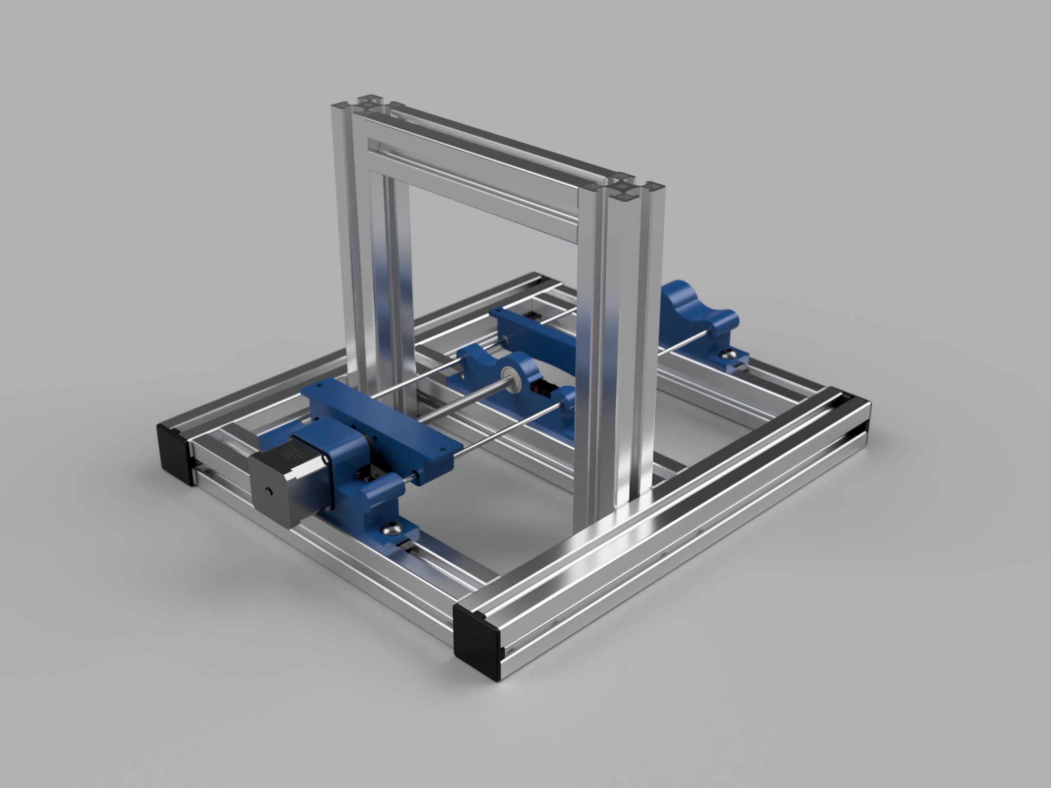
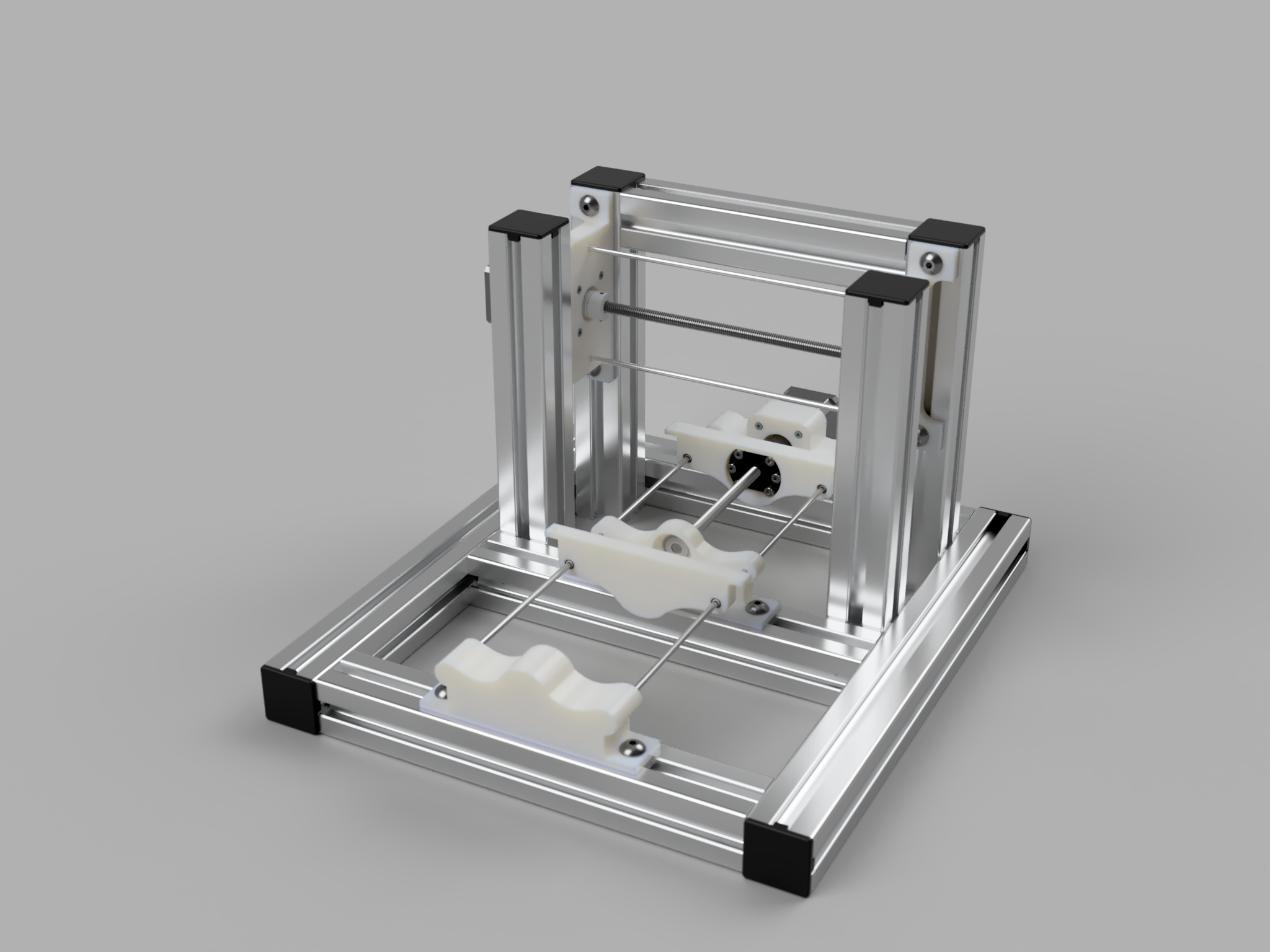
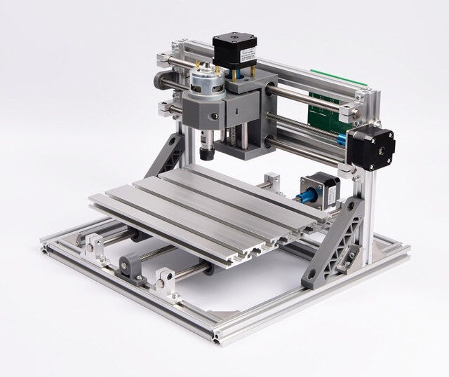
After cancelling the order that was clearly never going to arrive, an order from a new supplier has completed the y-axis for my homebuilt CNC mill.
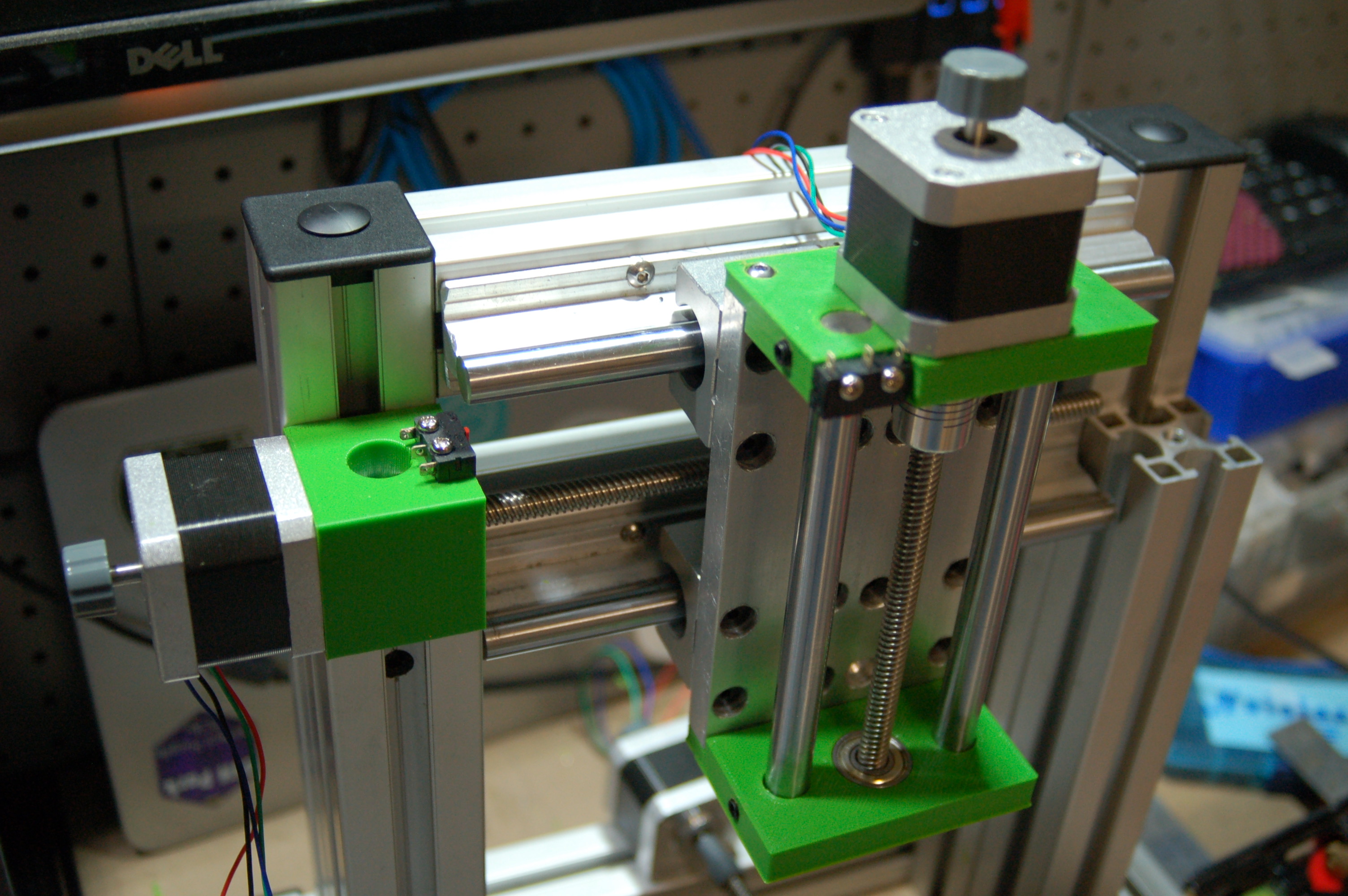
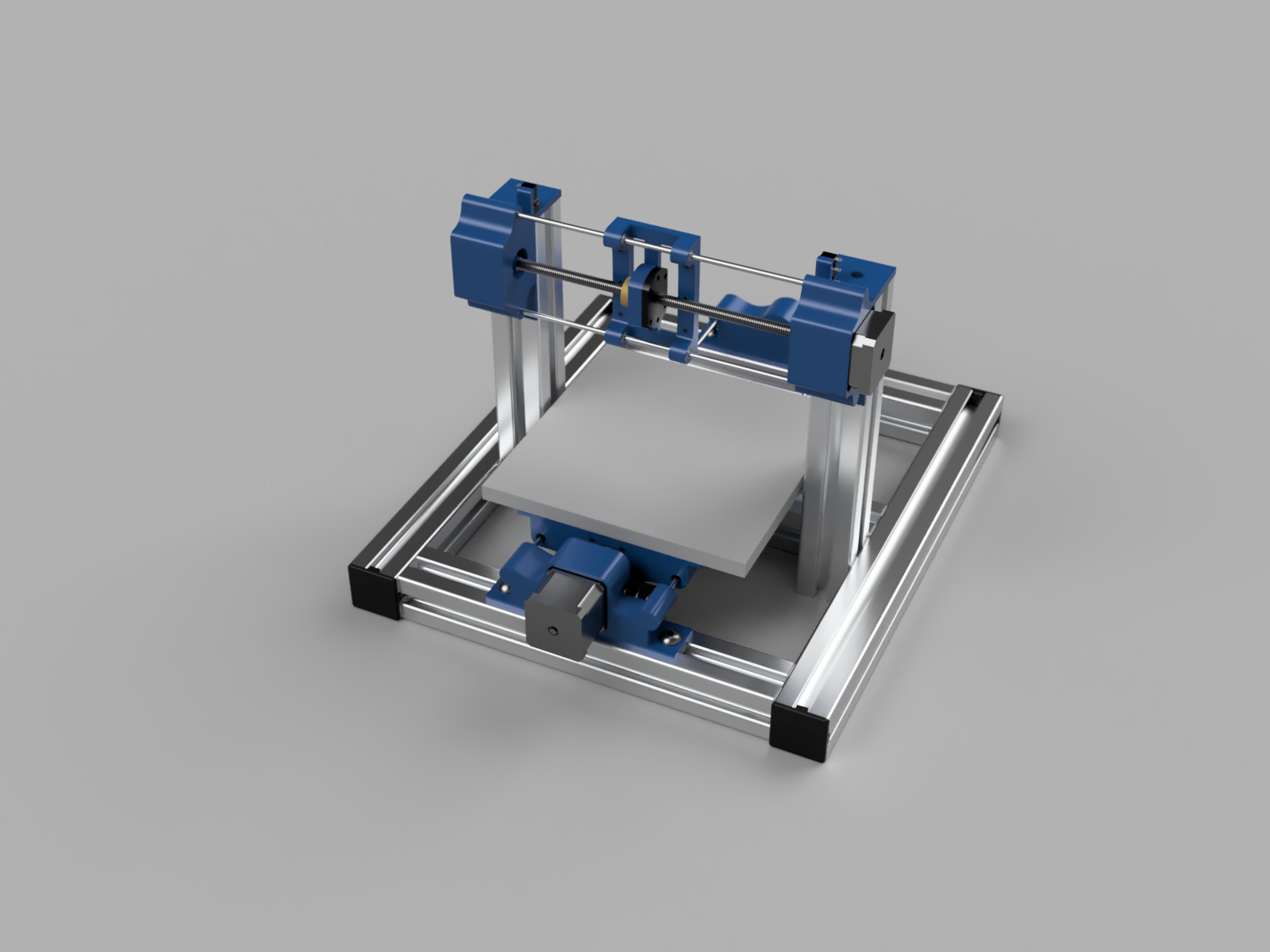
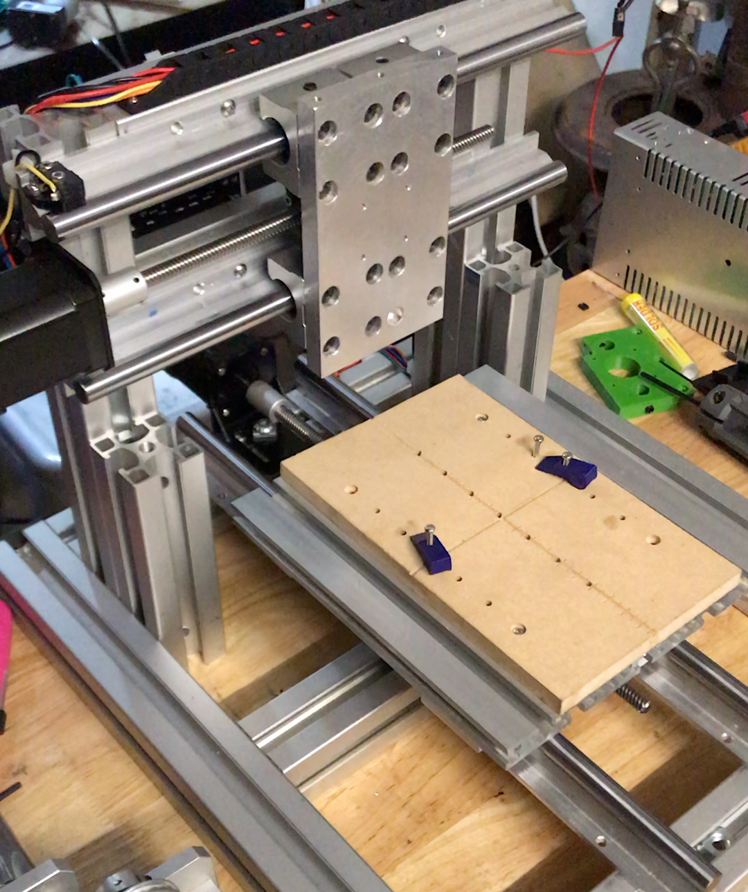
I used left over aluminium to create four adapters to hold the base board to the slides. I’m using a 200x180mm extrusion as it gives me a bunch of work piece holding options.
Once I assembled everything, I did notice a couple of issues.
The spindle isn’t centered
The spindle is about 20mm off centre in the Y direction, so I needed to adjust the position of the front brackets to stop them falling off when the y-axis was at full stroke.
This also meant I needed to move the end stop 20mm forward so the home position was in the right place.
Spindle travel
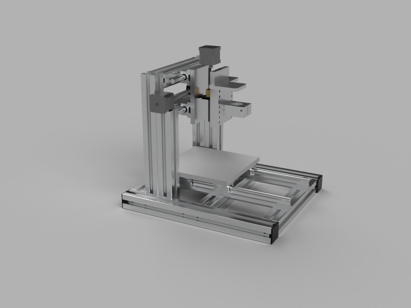
The spindle was too high. I was trying to avoid having to cut the vertical structs, but removing 40mm from all four seemed the easiest solution.
This does make using a vice a little less convenient, but the main use case for this mill will be PCBs so being able to get close to the spoil board is more important.
The lead screw saga
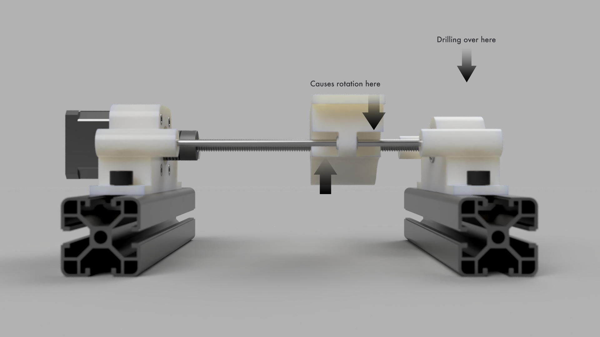
This issue was more annoying: the Y-lead screw was now too short. Completely my fault – this was 100% a design issue. At this point in the project I’d been riffing without CADing things first and didn’t realise that the position I had the anti-backlash nut lost 40mm of travel. Add another 20mm because of the spindle offset and I was 60mm out.
I discovered this by witnessing the anti backlash nut spring flying across the room as it spun off the edge of the screw.
So I had a conundrum. One of the design goals of this project was to reuse as much if the Makibox as possible. I had already replaced all the 4mm linear rods with 12mm linear rail, leaving just the steppers, lead screws and controller board.
I could either redesign the y-axis, which would require a bunch of replacement parts, waiting for said parts and time; or I could just buy a longer lead screw.
I found a 300mm T8x8 on EBay in Australia for $30 delivered and it could arrive in three days. I did this.
Alignment – Y axis
At this point I stripped everything back so I could align all the pieces.
I found a spare bathroom tile that I planned on using as a ground plane – it seemed flat enough for my purposes.
I started by squaring up the base frame using an engineer’s square.
Next a place one of the y-axis rails loosely in place using a 3D printed spacer. I dury rigged my depth gauge so I could dial it in – I got it to with in 0.05mm. Machinists would baulk at that but I’m fine with it.
I cheated a bit in the second rail: I simply put the bed on and rolled it up and down a few times to get alignment.
Finally I used the depth gauge to get the bed square.
